|
|
Post by Gary Davis on Dec 11, 2015 15:57:06 GMT -5
i love how you've used jigs to keep everything lined up and square.  duane It sure makes doing a build sooo much easier..... Hey KIP....Thank you for the compliment... |
|
|
|
Post by Gary Davis on Dec 14, 2015 19:59:21 GMT -5
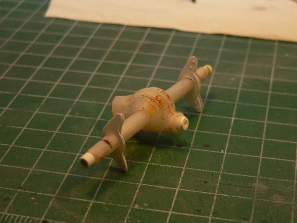
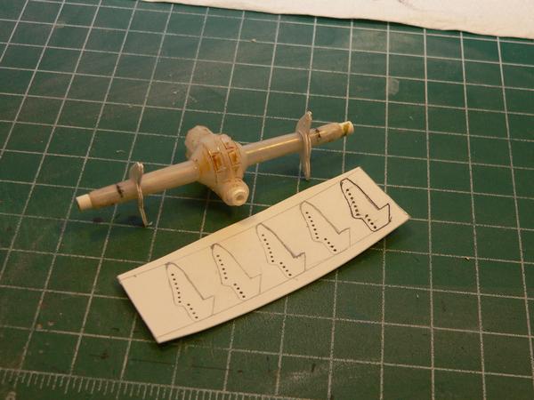
Got a little more done on the 4 bar rear suspension. The Axle and chassis brackets were drawn out on paper and then transferred to plastic and cut out. The chassis brackets aren't cut out yet. These are just in mock up to see how tight the bracket fit was on the axle. So far they look like they're going to work..
|
|
|
|
Post by Calvin on Dec 14, 2015 21:01:35 GMT -5
Impressive!
|
|
|
|
Post by Art Laski on Dec 15, 2015 2:06:55 GMT -5
Still continuing to impress, Gary!
|
|
|
|
Post by Gary Davis on Dec 19, 2015 20:05:27 GMT -5
Thank you for the comps Calvin and ART.
Well...The 4 bar suspension is finished being fabbed and in mock up.The bolts aren't in as this is only temporary. After it's all painted...they well be added...Thanks for looking in folks...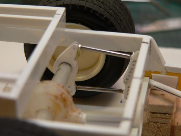 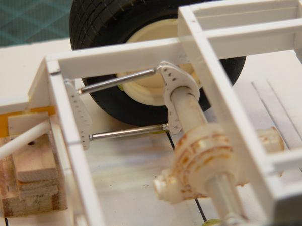 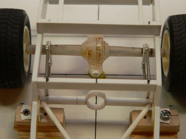
|
|
|
|
Post by Calvin on Dec 20, 2015 1:39:03 GMT -5
A lot of times I have to tell my eyes....YES! it really is true!
|
|
|
|
Post by Gary Davis on Jan 2, 2016 14:09:41 GMT -5
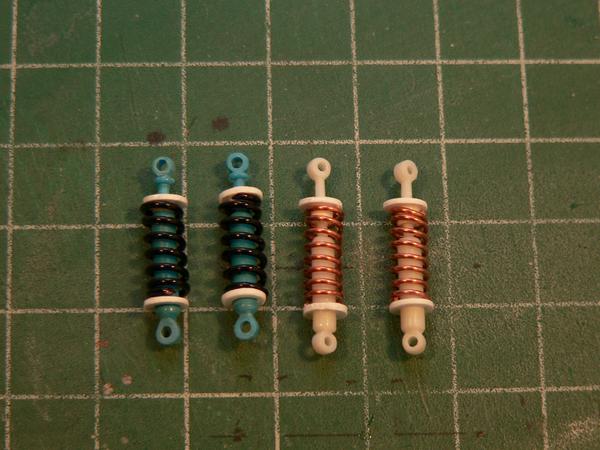
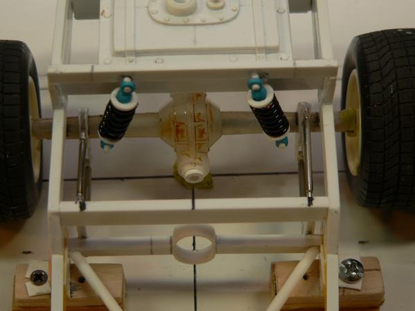
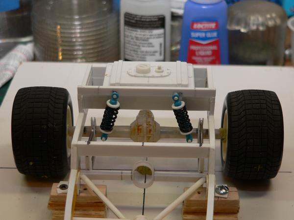
I managed to get a little building done during the Holidays. The coilovers(front and rear) were finished.The rear mounting bars for the coilovers were fabbed and they are mocked up in these pics. The white shocks are the front and blue are rears. As soon as the motor is set in it's permanent location( hopefully today) then I can get the correct length for the drive line. Then the interior sheet metal and bar work can begin...
The fabbed coil overs....
Rears mocked up....
|
|
|
|
Post by kip on Jan 3, 2016 18:05:31 GMT -5
Those coil overs are unbelievable. I'd pay to see a video of you making this. I would sure learn a lot.
kip
|
|
|
|
Post by Gary Davis on Jan 4, 2016 15:56:35 GMT -5
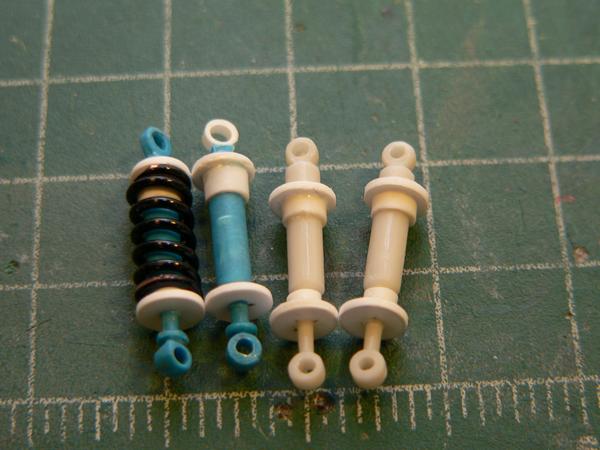
Hey Kip...I'll tell ya...I can operate a point and shoot camera...but doing a video is probably not a strong point with me. What I can do is explain the process for you, if that can be of help to you. First...I decided to use the shocks from the petty nascar kit (it was a parts kit I picked up at a show...for this reason). I measured the thickness of the shock body and found a piece of steel rod ( which I got from the LHS that deals in RC stuff...they carry ALL the steel wire that is used in RC planes,Boats ETC.) that was a little bigger than the body measurement. The rod was put into the vise and I found the size of wire that I wanted for the springs. I held on to one end on the vise top and started wrapping the wire around the rod. I made them long enough to do at least two springs. Then I cut them in half to make two springs. The front springs are a little smaller in Diameter than the rears. Then...the piston rod was cut from the shock body and the body was drilled out about 1/4 way for that shaft to adjust in and out. That makes mounting them a lot easier. The spring stops (discs) are sheet plastic that was punched out a little bigger than the spring diameter. They are then drilled out to the body diameter and also the piston rod diameter. They were then glued in place and all the parts were put together after that all dried. The mounting holes were also drilled out before the discs were glued on. Man...wrote a book here....I hope this will help you Kip(and anyone else). If you have any more questions...please fell free to ask any time...
|
|
|
|
Post by kip on Jan 4, 2016 17:54:16 GMT -5
Thanks Gary. It sounds like they really work in addition to being just beautiful.
kip
|
|
|
|
Post by Gary Davis on Jan 11, 2016 18:00:57 GMT -5
You are very welcome Kip.
I did get the engine in it's permanent location and that enabled me to set the correct length for the drive line.....
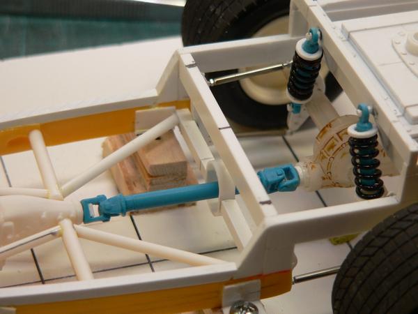
I also finished the shocks up(built the inner body on all four) and they are ready for paint....
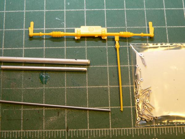
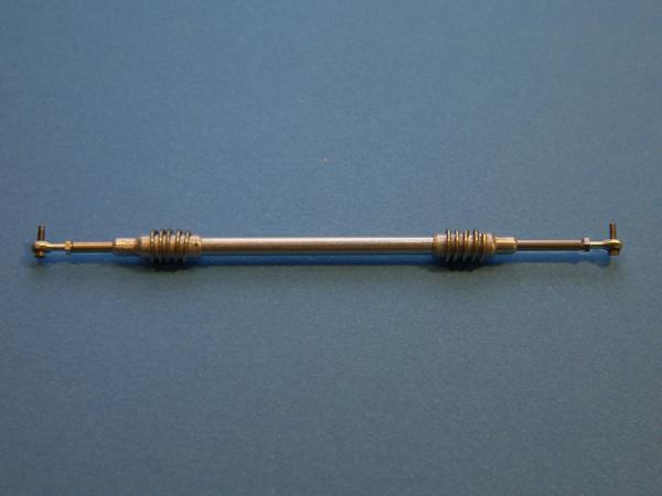
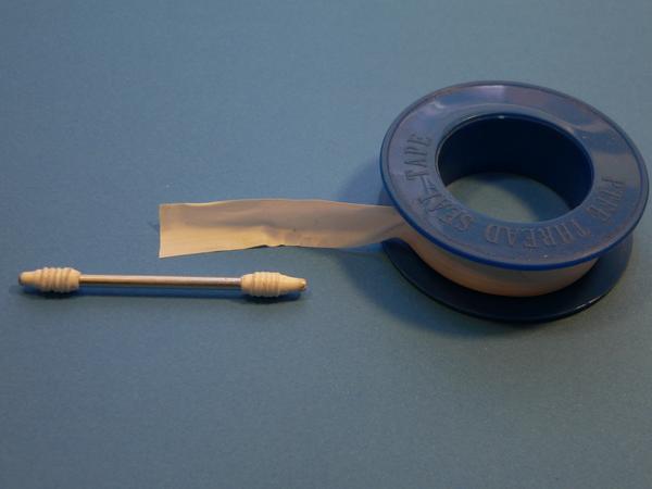
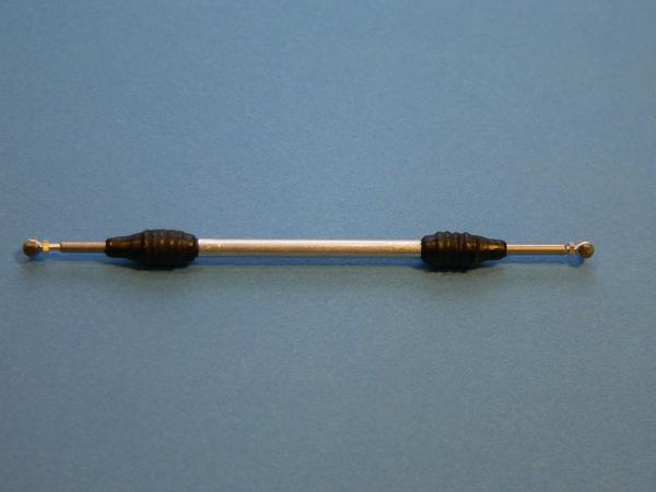
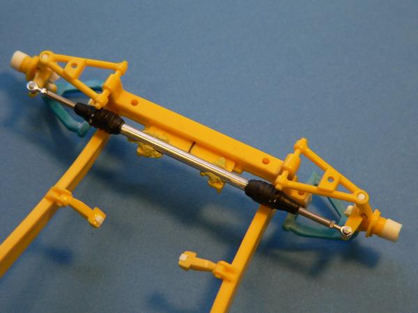
I also wanted to make the front wheels pose-able. So I decided to fab a Rack& Pinion steering system out of Aluminum and Stainless tubing. Rod ends are from RB Motion. I used the 34 ford system as a guide and over all lengths...here are a few shots of that progress....
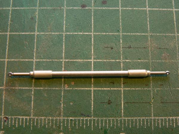
I used .020 wire to make the ribs and also used Teflon Tape to make it look like the rubber covers them. I then painted them flat black..
|
|
|
|
Post by Calvin on Jan 12, 2016 0:11:28 GMT -5
The tips and tricks you show are priceless! Actually you should charge people to see this stuff! You know!?!?!  |
|
|
|
Post by Gary Davis on Jan 22, 2016 14:06:13 GMT -5
Thank you for the comps Calvin....
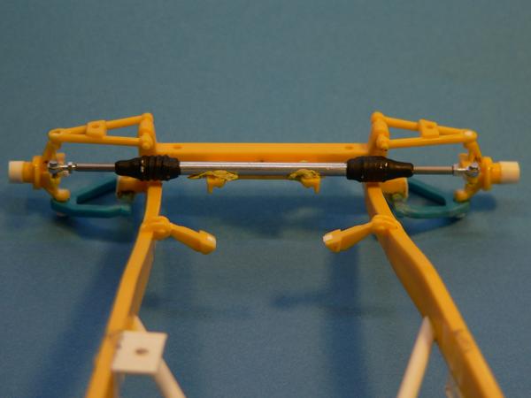
I managed to get the bracket for the rack onto the chassis. The system is mocked up in these pics.The bolts are threaded and will have the nuts on them at final assemble....
The original idea for headers was the use of solder, but.....I found a set in a parts Petty kit I thought I might try first....After extending each tube and mocking it up...I really didn't like how they looked....Soooo...I went back to the original idea of using solder. This is solid solder so I don't have to seal the ends off to keep Rosin from leaking out yrs down the road. The Curved out tube was a Plastic coat hanger turned down and then bent to shape (with heat applied) and then the ends drilled out. The collectors will be made with heat shrink tubing.
THE FIRST SET...
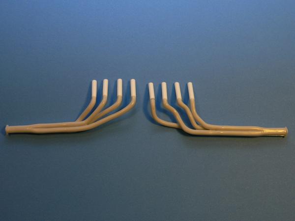
THE SOLDER SET.....
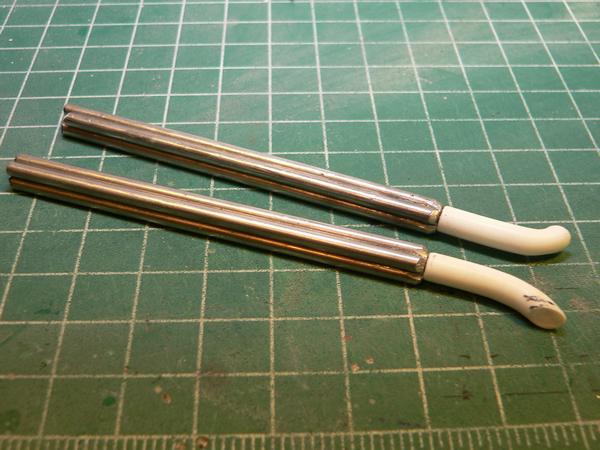
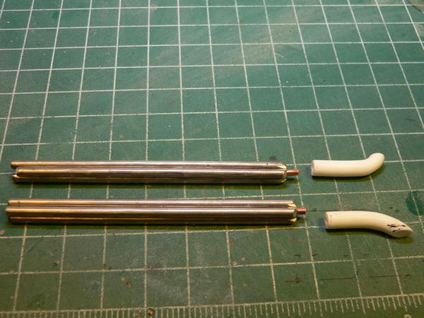
A jig will be made to bend the headers into the shapes that are needed to clear the body and be mounted parallel(as much as possible...) to the deck.....
|
|
|
|
Post by Gary Davis on Jan 23, 2016 14:14:42 GMT -5
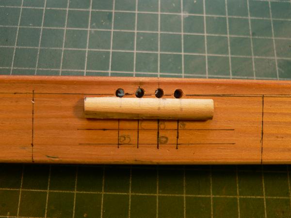
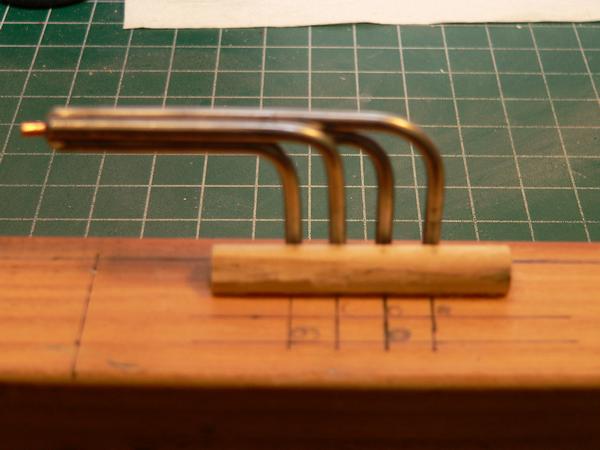
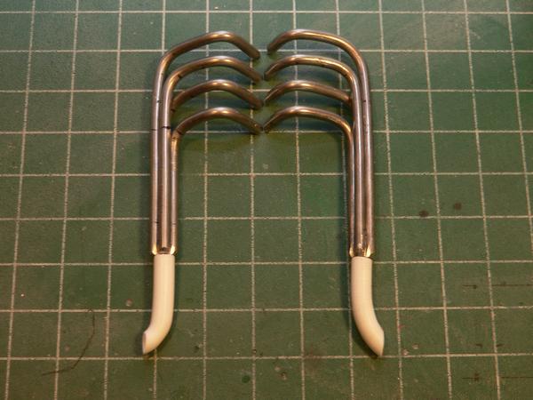
A little update here... I made the bending jig for the headers out of a 2x2x6 and a 5/16 dowel. It worked real well for making that final bend. Here are a few pics of the progress...
The bending jig...
Headers after the first bend(a 1/4" rod was used for this)...
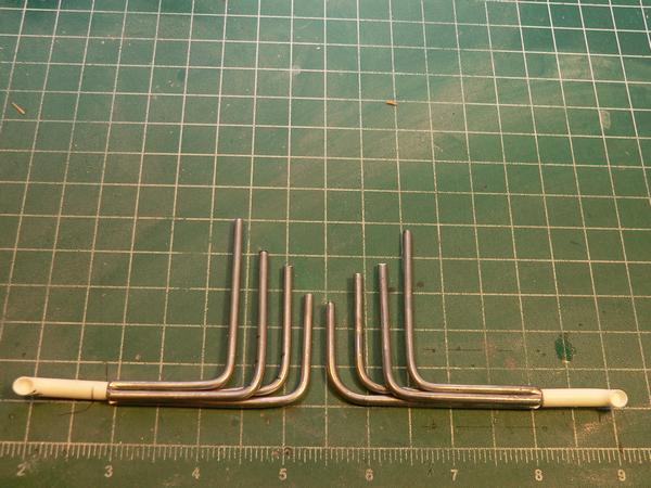
In the jig and after the second bend....
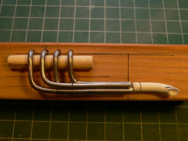
Mocked up on Engine....
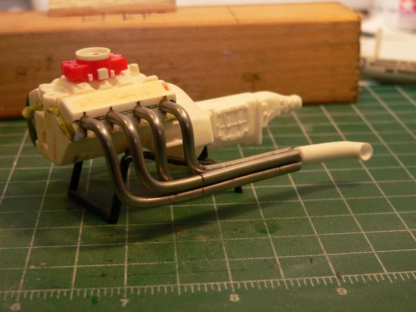
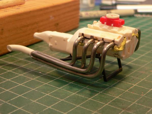
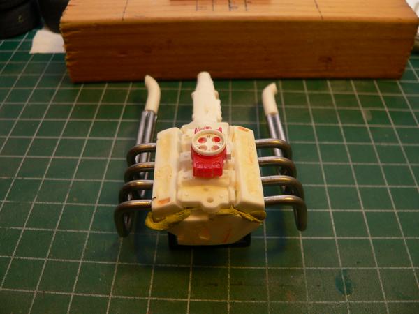
The good thing about using solder is that small adjustments can be made pretty easy. I still need to drill out the heads where each tube hits as that will give me more "bite" when they are glued.
|
|
|
|
Post by kip on Jan 23, 2016 15:23:44 GMT -5
They look great. I like the idea of using solder but I am clumsy and I am afraid by the time I was done with the build they would be 8 separate shapes.
kip
|
|
|
|
Post by Gary Davis on Jan 23, 2016 20:21:29 GMT -5
Thanks Kip...it's not as difficult as one might think...
Here are a few more pics with the engine mocked up in the chassis....
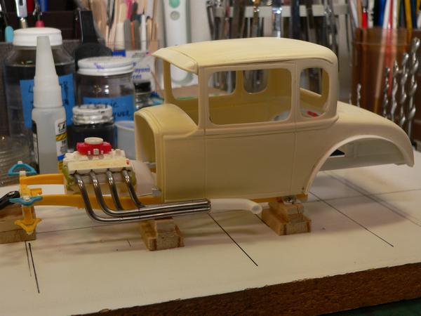
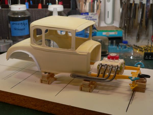
|
|
|
|
Post by racerbrown on Jan 23, 2016 20:29:46 GMT -5
Great results from a nice simple jig!
Thanks for sharing.
Duane
|
|
|
|
Post by Art Laski on Jan 24, 2016 22:14:50 GMT -5
Great stuff, Gary!
|
|
|
|
Post by Gary Davis on Jan 26, 2016 15:43:48 GMT -5
Thanks Duane and ART....Got more done on the headers...they're all together to include the collector. Haven't taken pics as it's a small update. But...they(the headers) are ready for priming. Man...it's going to be good to see some of this build ALL one color...Thanks for looking in on this project Folks....
|
|
|
|
Post by Gary Davis on Jan 30, 2016 16:53:27 GMT -5
Here's an update on the engine....I did get the collectors on the headers. They are ready for paint at this point.....
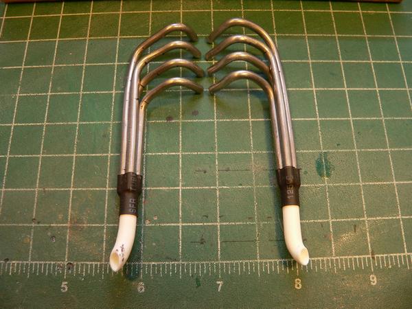
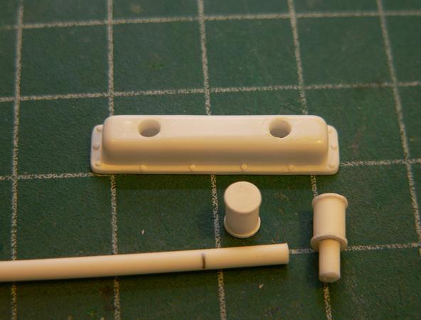
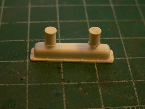
The valve cover breathers were fabbed from Plastic rod and the bottoms and tops are punched sheet plastic...
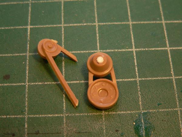
The front pulley assy. and Dist. from a 65 stang is being used for this engine. The Alt/Gen was cut off and a small belt fabbed. This car will not run with a fan. The water pump was cleaned up...bushing added(plastic rod) and drilled out for the pulley Assembly.
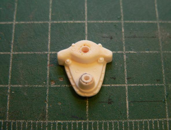
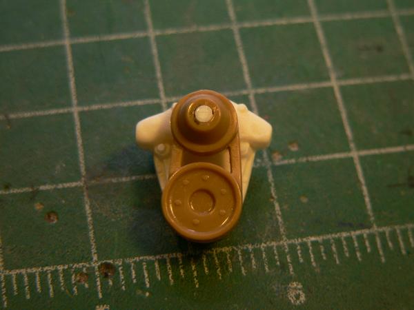
This engine is ready for primer. Then the paint will be shot.
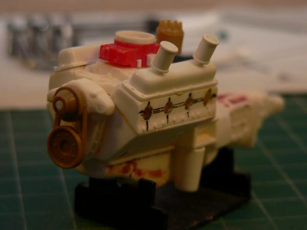
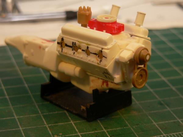
As always...thanks to ALL who stop in to have a look and comment on the progress....more to come...
|
|
|
|
Post by sandysixtysfan on Jan 30, 2016 18:21:56 GMT -5
This is looking so good and the headers are really amazing.
Sandy
|
|
|
|
Post by Gary Davis on Feb 13, 2016 14:20:29 GMT -5
Thanks for the comps Sandy
Here's an update...The radiator was sourced from a 65 Mustang parts kit. I didn't like the gaping hole on the back side so I trimmed down another radiator and slid it into that whole. Much better...
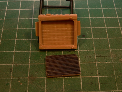
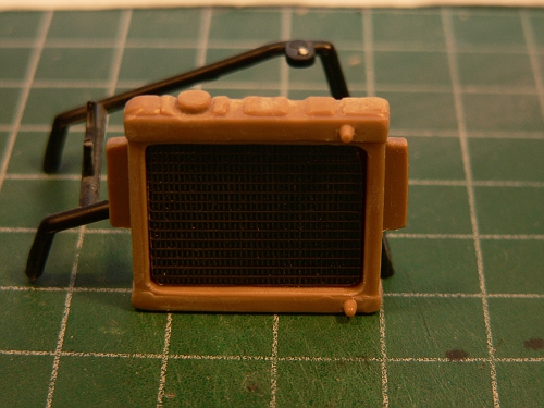
The Distributor was also sanded and cut to give it a cap. Wires will be added with boots. The wire in this pic was a test shot...
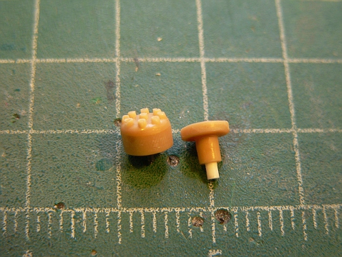
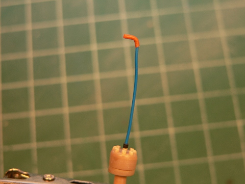
On the chassis...
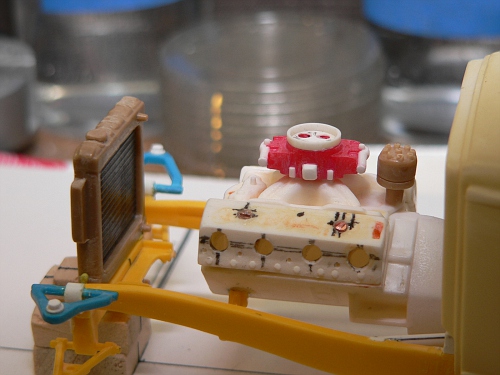
The front Grill was also worked on. It is in mock up and needs to be dropped down at least another inch..maybe 1 1/2 (scale). The hood will either be Vacuum formed (over a buck) which will give longer sides or...I can fab one from sheet and hand bend it to fit on the top only..Like the paper mock up is in the pic. The collectors on the headers were also put on....
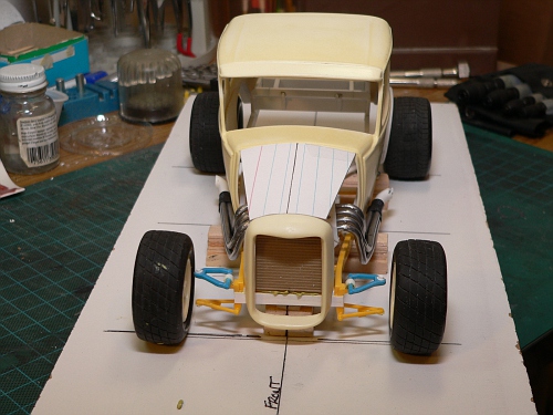
At this angle...you can see what I mean about dropping the grill down more....
Thanks for looking in and commenting folks....
|
|
|
|
Post by Art Laski on Feb 13, 2016 20:40:05 GMT -5
Nice work, Gary!
|
|
|
|
Post by racerbrown on Feb 14, 2016 0:03:23 GMT -5
looks great gary!
i agree with you on the grill.
it'll make it look more racy.
duane
|
|
|
|
Post by kip on Feb 14, 2016 8:40:22 GMT -5
I've been anxiously waiting for an update. Absolutely out of this world detail. Looking really, really good.
kip
|
|
|
|
Post by clm1545 on Feb 14, 2016 10:22:06 GMT -5
It's really coming along, Gary, Great work. I am a little bit confused (happens a lot) about the engine, what is it?
|
|
|
|
Post by Gary Davis on Feb 14, 2016 13:01:29 GMT -5
Thanks For ALL the Comps folks.
Hey Duane...I did get a section cut out of the Grill. I'll post pics of that a little later.It still looks like a street car some what.
CLM...that engine is going to be an open comp big block. The block it self is from a 57 Chevy parts kit I got at a show, stripped and re-worked.
|
|
|
|
Post by Gary Davis on Feb 23, 2016 22:23:50 GMT -5
Here's an update for this guy....I did take a few scale inches out of the Grill surround. It sets higher and just in line with the front bars. The grill area....   The front push bars,cowcatcher,chrome horn or what ever it's called in your area :-D ...was fabbed and is in mockup...It's pinned so it can be removed for painting and then re-attached afterwords.... 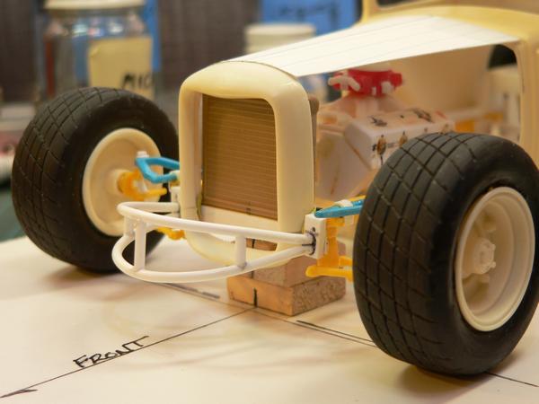 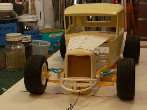 The rear bars were also fabbed and are in mockup the same way(pinned)... 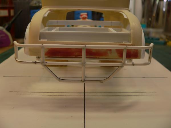 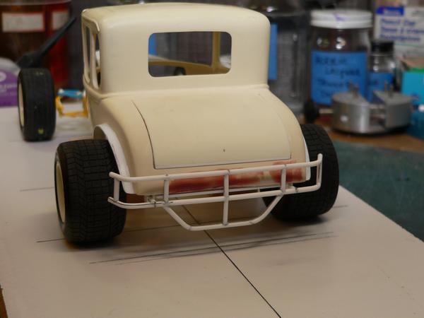 With that work completed...I can NOW concentrate on the interior floor and bar work...Thanks for stop'in by and look'in around... |
|
|
|
Post by Gary Davis on Mar 4, 2016 14:22:35 GMT -5
Here's a few looks at the interior floor and tranny tunnel. I took the seat out of the 34 Rod kit and it needs Modified. Now I need to get the firewall and the back wall built...then the bars will go in. Thanks for stop'in by and look'in.... 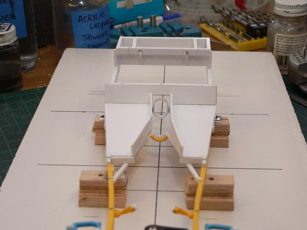 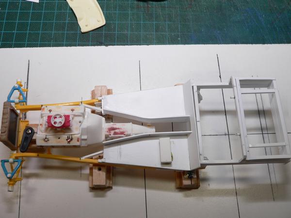 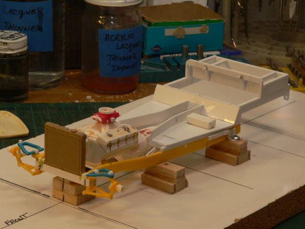 |
|
|
|
Post by Gary Davis on Mar 5, 2016 19:27:57 GMT -5
Here's a small update to show that I did build something today...LOL..
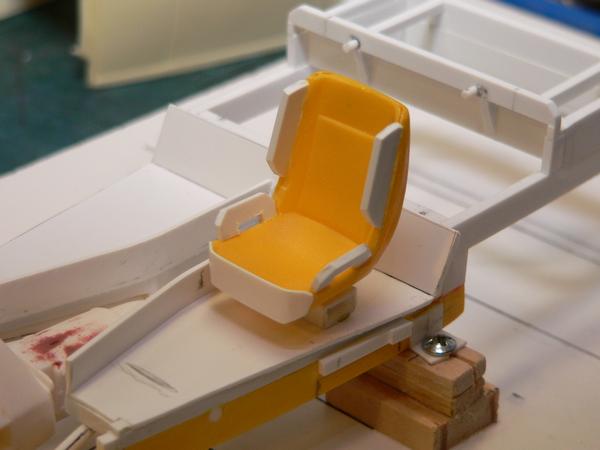
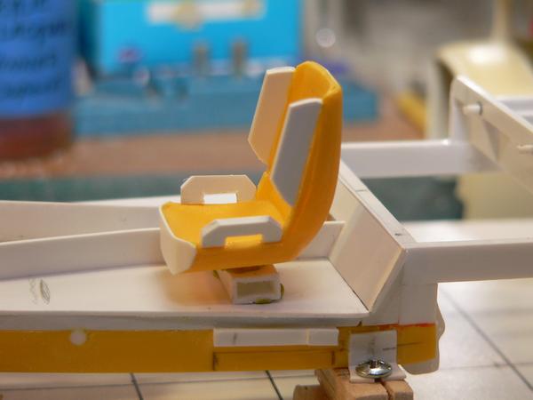
I took the seat from the 34 Rod kit and made it into a Racing seat. The seat is in mockup as I just finished with all the fab work. Now...it's sanding to shape time. Here's a few pics for a look...
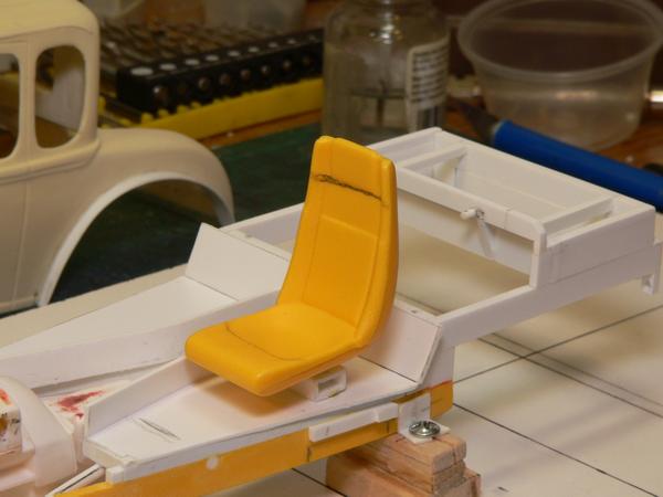
Thanks for look'in in.....
|
|