|
|
Post by Gary Davis on Nov 7, 2015 19:45:10 GMT -5
|
|
|
|
Post by clm1545 on Nov 7, 2015 20:18:09 GMT -5
That is quite a project, Gary. Resin Body, I assume?
|
|
|
|
Post by Calvin on Nov 7, 2015 22:59:03 GMT -5
Wow! This is going to one heck of a project!
|
|
|
|
Post by Art Laski on Nov 8, 2015 2:04:40 GMT -5
Going big on this one, Gary! Looking forward to it.
|
|
|
|
Post by racerbrown on Nov 8, 2015 7:50:06 GMT -5
yeah gary!
fantasy build? or are you doing a specific car.
duane
|
|
|
|
Post by alterrenner on Nov 8, 2015 8:43:09 GMT -5
This is going to be good! You've already got me hooked with the 1/16 scale 2 X 6 wooden blocks to support the frame from the "floor"!
--Frank
|
|
|
|
Post by Gary Davis on Nov 8, 2015 17:15:57 GMT -5
CLM...the body is a Resin RMR BODY yeah gary! fantasy build? or are you doing a specific car. duane It's going to be a build of a car I would build and drive in today's vintage racing series. The dirt guys do put on a fairly competitive racing show. I found this pic of a dirt modified a few yrs back and it inspired me to build this. Here's the car.. 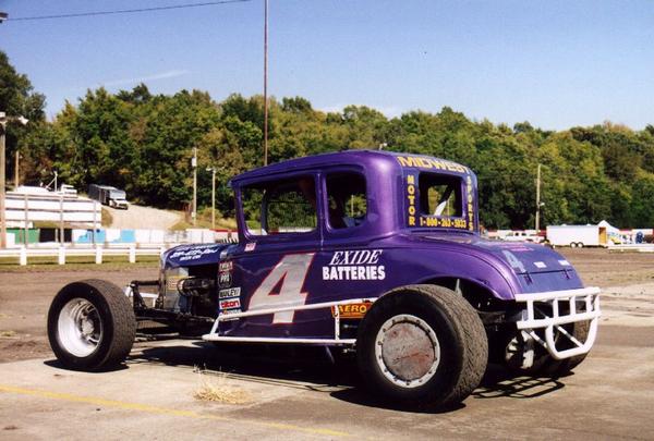 |
|
|
|
Post by alterrenner on Nov 9, 2015 5:57:14 GMT -5
Why the cover on the left rear wheel? I can see why on the right side, to keep the dirt from building up, but was the left side as prone to the build-up, too?
--Frank
|
|
|
|
Post by Gary Davis on Nov 9, 2015 19:41:24 GMT -5
Hey Frank...Damn good question... I'm with you on that one. The only thing I can surmise is that they thought that it would help to keep dirt from the inside of that side...LOL...I guess thinking about keeping weight off of the car leads to that. I really haven't seen to much dirt in the left rear...but ya never know....right?
|
|
|
|
Post by alterrenner on Nov 10, 2015 6:03:46 GMT -5
A device to keep from losing the lug nuts?
A concrete weight to get the car through tech"?
Hub covers sold in sets of two?
An abnormal fear of another car scratching the new wheel?
Had a hard time balancing the wheel?
Something to do with the Exide battery (lead plates, you know)?
The plate is connected to a hydraulic, extending ram?
No place to keep the stash inside the car when it was brought up from Mexico?
SOMEBODY STOP ME!!
--Frank
|
|
|
|
Post by alterrenner on Nov 10, 2015 6:51:57 GMT -5
All they had was a right rear wheel for the photo shoot, and the right side of the car was bashed in, BAD!
You wouldn't believe how bad the thing pushes without that left rear weight bias!
HELP!
--Frank
|
|
|
|
Post by Gary Davis on Nov 10, 2015 14:08:14 GMT -5
A device to keep from losing the lug nuts? A concrete weight to get the car through tech"? Hub covers sold in sets of two? An abnormal fear of another car scratching the new wheel? Had a hard time balancing the wheel? Something to do with the Exide battery (lead plates, you know)? The plate is connected to a hydraulic, extending ram? No place to keep the stash inside the car when it was brought up from Mexico? SOMEBODY STOP ME!! --Frank LOLOLOLOLOLOL...man Frank...you had me laughing pretty good there. My wife had to come see what the heck was going on!!! LOL I'd probably go with ALL THE ABOVE!!! |
|
|
|
Post by clm1545 on Nov 10, 2015 16:41:38 GMT -5
Is it time for a medication adjustment, Frank?  |
|
|
|
Post by Gary Davis on Nov 11, 2015 16:31:08 GMT -5
Here are a few update pics to show the fender wells and the windows opened up. The Wheels and tires and the motor are in mock for measurements.
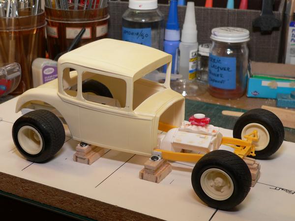
The wheels and Tires are made here in the shop...
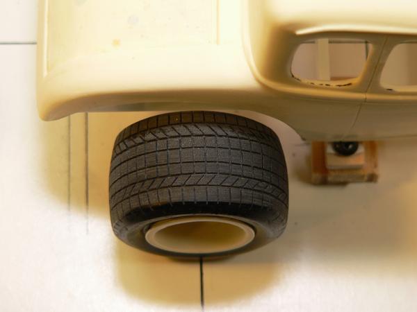
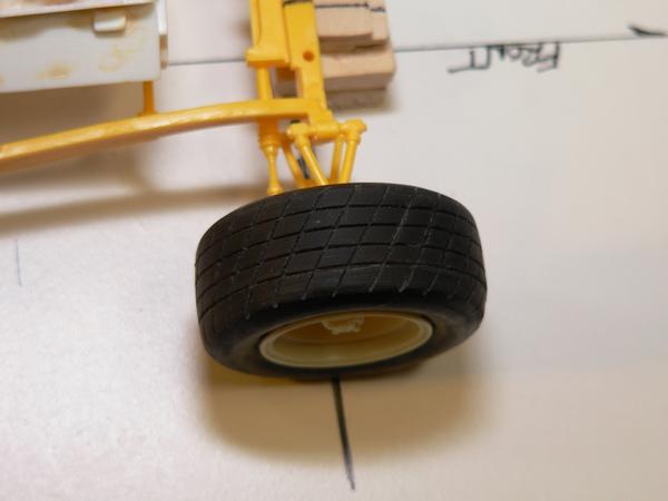
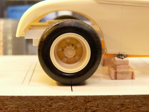
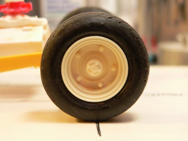
|
|
|
|
Post by Gary Davis on Nov 16, 2015 20:36:46 GMT -5
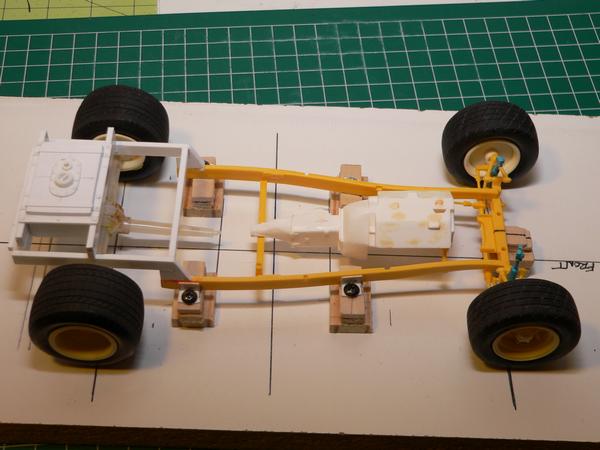
Here's a small update...The fuel cell was finished today. The shocks are in mock up for measurements. I'll probably build all four shocks as it's easier to attach them if they are able to move in and out. here's a look at what's done...
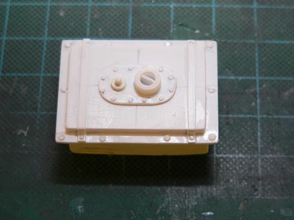
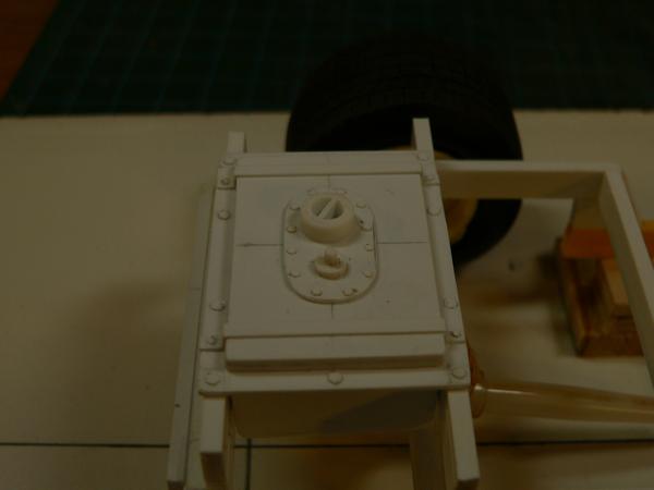
|
|
|
|
Post by clm1545 on Nov 16, 2015 22:13:04 GMT -5
Nice work, it's looking good.
|
|
|
|
Post by racerbrown on Nov 16, 2015 23:23:28 GMT -5
looking good!
i'd love to see a WIP on how you made the tires and wheels.
duane
|
|
|
|
Post by kip on Nov 17, 2015 12:57:12 GMT -5
and the shocks.
kip
|
|
|
|
Post by Art Laski on Nov 17, 2015 13:38:58 GMT -5
Love the tires and wheels, Gary! I agree with Duane, I would love to see the process to make those. Any pictures?
|
|
|
|
Post by Gary Davis on Nov 18, 2015 14:30:58 GMT -5
Thanks for the compliments folks. As far as a WIP on the dirt tires...That's a whole NEW subject that will take time that I don't have right now. But....I can tell you how I made them and you's can go from there.. First off....I turned the tires on the lathe.At this point they are Asphalt tires. I made a mold( RTV Rubber) of them and poured the mold with tan resin. Then I measured the width and circumference of each tire. Laid a piece of wide masking tape on a thick piece of glass(a smooth piece of plastic will also work) so the tape won't lose to much tack. Draw the width(foot only...not including the side walls) and Length on the tape. I then divided the length into as equal parts as possible. Then the tread pattern is drawn on the tape using a very fine point sharpie. The tape ( pattern) was then cut from the wide tape and transferred to the resin wheel. The tire is then put into a small vice( soft jaws work good here). NOW...this is where it really gets fun....With an xacto knife...cut into the resin tire thru the tape and the pattern, making sure that the pattern is transferred to the tire. I usually do the vertical lines first and then go back and to all the horizontal lines working from the center of the tire outwards. Now that all the lines have been transferred to the tire...All the cut pieces of tape can be removed and the pattern should be transferred to the tire. Now..I use a fine blade Razor saw and repeat the same process as in the pattern transfer step. This is where the amount of strokes gives the depth that is wanted in the tread pattern. After the tread pattern is completed...I usually go over the tire with a light sanding to smooth it all out. Now....a New mold ( RTV Rubber) is made of the Dirt tire and it is poured in a Black Urethane hard rubber. All in All...it took me about 2 days just to do the tread pattern on one rear tire. I made two different widths of rear tires. The front took about 4-5 hrs. Here's a pic of the three Resin Masters.... I hope this helps anyone who is interested in doing their own tires... 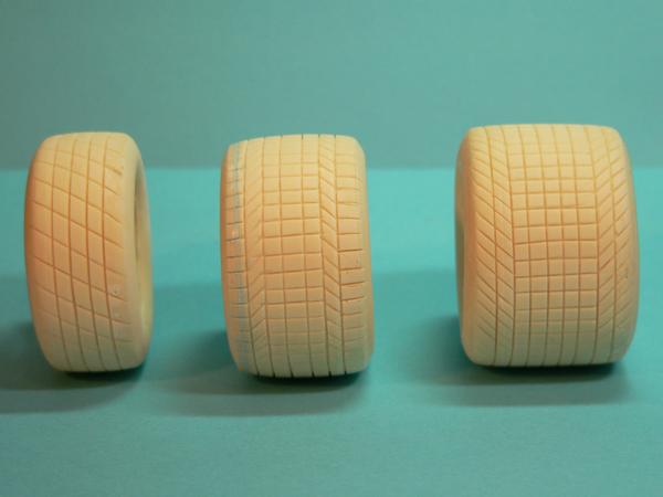 |
|
|
|
Post by Art Laski on Nov 18, 2015 15:23:29 GMT -5
Thanks for the write-up, Gary. I've made my own tires a couple of times, and it seems to me the hardest part is getting the initial shape correct. You nailed it on these. What material did you start with that you turned on the lathe?
|
|
|
|
Post by Gary Davis on Nov 18, 2015 16:04:47 GMT -5
I hear you on the sidewall (or shoulder) of the tire. I made a special tool just for that. In-fact....I think I had to make two. The first one was a little thin at the apex and it snapped when I started to apply pressure as it was turning. I've got a keeper now. That's not one of my favorite things to do...make tools to make parts...LOL...but...If a person wants to build something that's not manufactured...that's what ya gotta do.... OH yea....the material I used is UHM ( I think that's correct...it's been to long) plastic rod that I bought at a Plastic store here in Tacoma. Here's a look at All the masters(asphalt) that I made. Also...some of these are turned to look like the Asphalt Super Modified tires that are fairly wide.They range from 1/24-25 ...1/16...1.12...1/8 scales. I don't have the 12th and 8th scale stuff in molds as of yet. Here are a few pics of them.... 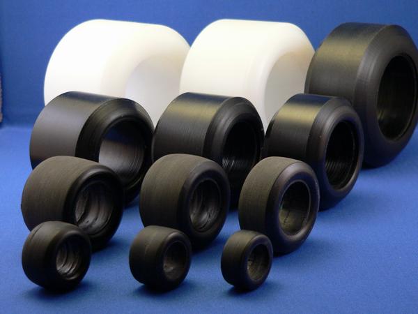 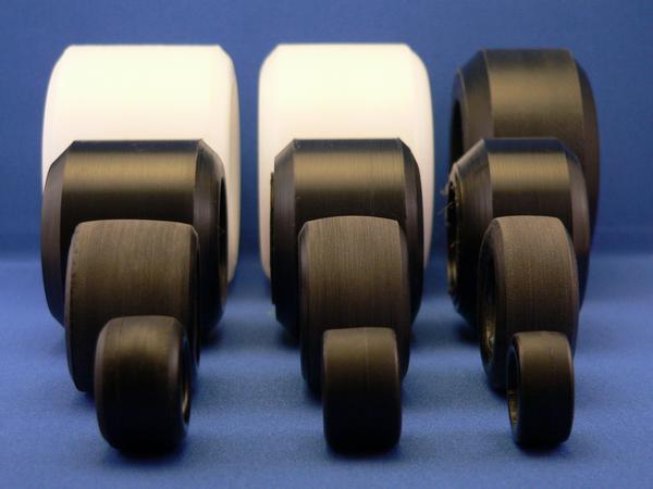 |
|
|
|
Post by clm1545 on Nov 18, 2015 17:22:51 GMT -5
WOW, just WOW.  |
|
|
|
Post by racerbrown on Nov 18, 2015 20:01:26 GMT -5
what craig said!
duane
|
|
|
|
Post by Gary Davis on Nov 20, 2015 18:56:49 GMT -5
Here's a little update.....I added fender flare material to the rear fender wells. They will be about 3" wide when finished. 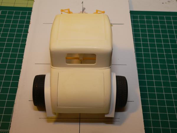 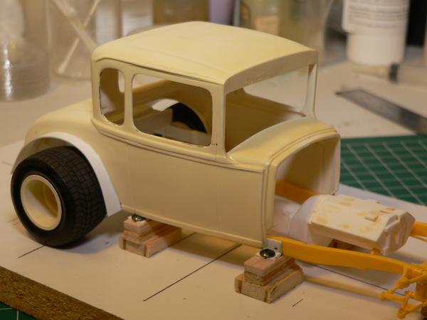 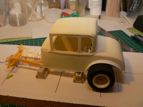 Also got the U-Joints fixed and the torque tube removed.... 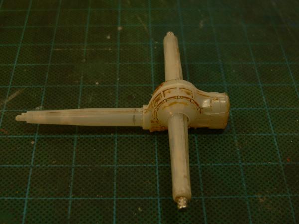 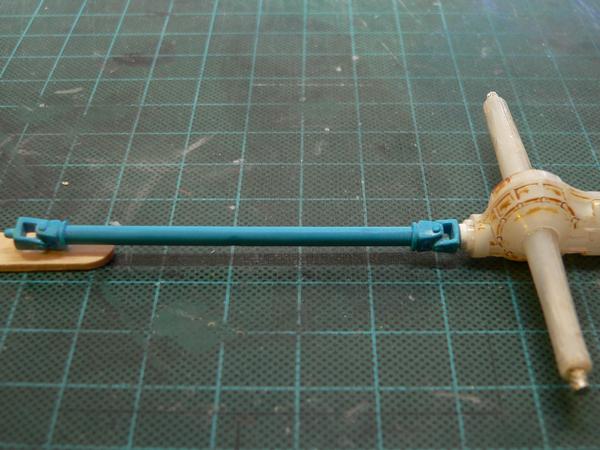 I won't be using the whole length of that drive line. Actually I'll only be using the U-Joints...I will make the drive line as it will be a whole lot shorter. Just posted pics of the progress on hogg'in out the joints. |
|
|
|
Post by Gary Davis on Dec 5, 2015 17:14:50 GMT -5
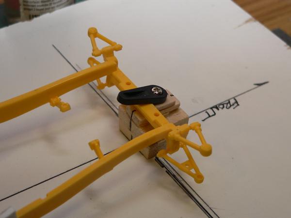
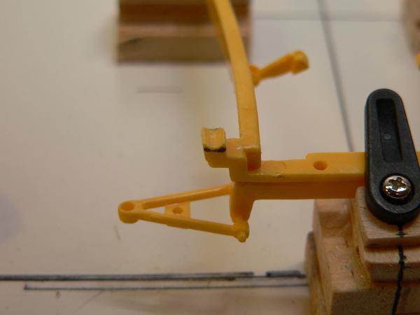
Here's a small update... I removed the upper "A" arms and prepared the new "A" arms(from a Petty kit) to fit this chassis.The shocks that I decided to use are also from the Petty kit. The pics show the shocks before and after. The coil springs were made by wrapping wire around the correct size rod. This is all in mockup and will be adjusted as I go.
The "A" arms before and after being removed...
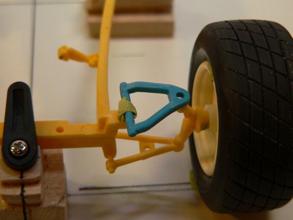
front shocks with coil springs....
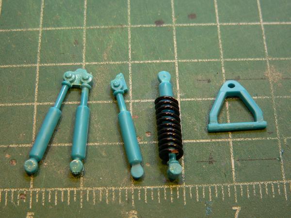
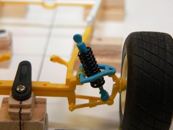
|
|
Deleted
Deleted Member
Posts: 0
|
Post by Deleted on Dec 6, 2015 7:30:00 GMT -5
Dang! When I saw the 1:1 purple car my brain screamed "Hot Heap"!!!!!
Seeing these builds makes me want to start a new hobby! How in the world?!?!?! !!!!!
|
|
|
|
Post by Gary Davis on Dec 10, 2015 20:46:41 GMT -5
Second time around on this update.....Dang computer anyhow....LOL OK...here's another Chassis update. The front "A" arms on. Also the back bar and drive line hoop were built and installed. Then the cross bars were then fabbed and added. Now with that finished...I can set the Q.C. in place and build the 4 link suspension. The Back coil over shocks will be added(built) after that is complete. Here's a few pics of the progress..... The permanent "A" arms.. 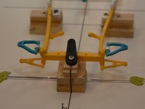 Back bar and drive line hoop... 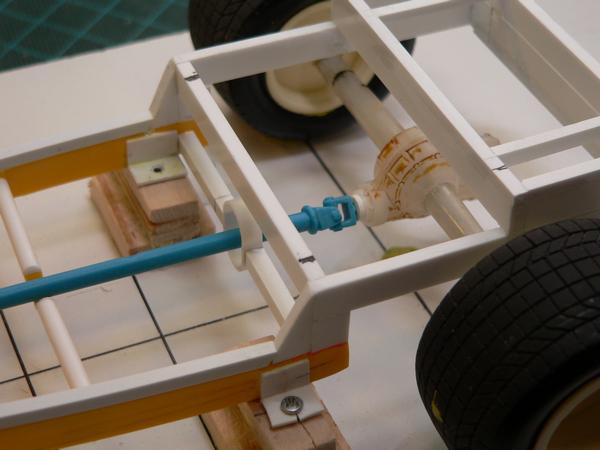 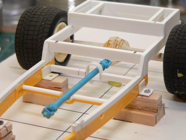 The X bars built and added... 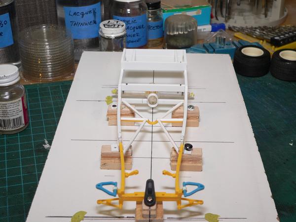 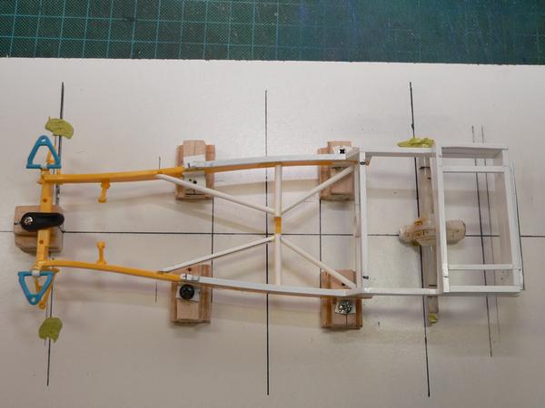 Thanks for looking in on this build folks..... |
|
|
|
Post by racerbrown on Dec 11, 2015 7:13:31 GMT -5
i love how you've used jigs to keep everything lined up and square.  duane |
|
|
|
Post by kip on Dec 11, 2015 8:14:31 GMT -5
Its fun to watch a true master at work. WOW
kip
|
|