Deleted
Deleted Member
Posts: 0
|
Post by Deleted on Sept 17, 2014 14:33:51 GMT -5
Thank you very much... My solder's temperature is surely far above 70°C... I'm going to test another solder with less power, I will let you know... Continuing with the building, as I said before, let's see the dashboard... here is the part provided by the kit:  It reminds me the years when I painted the dials simply in silver... At a first moment, I drilled all the five dials...  ...then I realized that the dial pattern was wrong, so I puttied the two external ones and glued a plasticard biece behind the dash...  ..then I made the hole for a fourth dial in the correct position...  at this point, the dials were too deep to put a decal inside, so I had to reduce the deepness with some styrene "pills" cut with the tool that you use to make holes in the belts (sorry, I don't know the english word)...  I painted the whole part, and I placed the decals in the smaller dials taking them froma the spare box... I had no white dial decal for the rev counter (quite big), so I painted the dial by hand, and I placed over it a "lens" cut in acetate with the same tool as above... the I glued the dash in place... on the left you can see the big (start?) button...  as I noticed tha the feet zone would have been visible from the cockpit, I scratchbuilt something that looked like pedals...   ... and I added the throttle and clutch cables..  I glued the pedals in place, I passed the cables through two guide rings and I glued the cockpit in place...  Then I added the seat... this had been previously covered with silk taken from a pair of my wife's old trousers, applied with vinyl glue...  ...then painted in the typical Ferrari racing seat blue of the era... I left on purpose some wrinkles in the tissue, that were slightly dry-brushed in light blue...  ... as you can see on the seat glued in place.  In the next posts we will see the work on the body... |
|
|
|
Post by Calvin on Sept 17, 2014 17:44:05 GMT -5
After you are done people are going to think it was an MFH kit!
|
|
Deleted
Deleted Member
Posts: 0
|
Post by Deleted on Sept 17, 2014 18:18:32 GMT -5
ah, ah, ah.... many thanks Chap, but you are too kind...
I simply like to try to improve with today's media old and/or rare and/or not too much expensive kits...
|
|
|
|
Post by racerbrown on Sept 18, 2014 6:51:39 GMT -5
i love how you did that seat.
duane
|
|
Deleted
Deleted Member
Posts: 0
|
Post by Deleted on Sept 18, 2014 11:34:12 GMT -5
Thank you Duane... after having completed the assembly of the suspenions and the cockpit on the lower body half, I completed the upper half with a "simulation" of the engine air intake trumpets, in the oval holes of the body... As the real car had two "covers" on the carburetors, painted in the same color as body, that let out only the trumpets, i decided to reproduce something like that, that could be visible through the mesh that will go over all... So I took two styrene pieces and I drilled three holes in each piece... to be sure to make the holes at a constant interval, I made them with increasing diameters drills..  ..then I glued a piece of styrene tube in each hole and I flared the upper end of the tubes with a mill..   After this, I glued the two assemblies to the inner side of the upper body half, being careful to respect the original misalignment (the right cylinders slightly forward in comparison with left cylinders)  And finally, I began to close the body, first with glue...  ... and the with soldered points:  |
|
|
|
Post by alterrenner on Sept 19, 2014 5:25:31 GMT -5
So, the secret of soldering white metal is to decrease the damage, and holding your breath? The last time I soldered white metal, it had melted before the soldering iron tip had even touched the metal! What soldering iron do you use?
|
|
|
|
Post by alterrenner on Sept 19, 2014 5:33:29 GMT -5
Sorry for the double post, and commenting on an old subject. My computer just displayed the second page...
|
|
Deleted
Deleted Member
Posts: 0
|
Post by Deleted on Sept 21, 2014 10:57:52 GMT -5
|
|
Deleted
Deleted Member
Posts: 0
|
Post by Deleted on Sept 21, 2014 11:54:09 GMT -5
Let's go on... After the main horizontal line between the the upper and the lower part of the body, I scribed the vertical lines... from forward to rear, the two double lines represent in fact the metallic belts that holded the fuel tanks, while the last is the separation lines between the fuel tanks and the engine fairing...  I also added two lower horizontal lines to make a limit for the lines above...  Then I marked the points to drill the holes for the rivets of the fuel tanks...  I made the rivets with some little brass nails... i used the rods by cutting the heads, then I sanded them...  to be continued... |
|
|
|
Post by Calvin on Sept 21, 2014 14:07:20 GMT -5
WOW! Impressive!
|
|
Deleted
Deleted Member
Posts: 0
|
Post by Deleted on Sept 27, 2014 11:04:30 GMT -5
thank you very much Chaparral! After the scribing of the side lines, I faced the issue of the separation line between the cockpit/nose fairing and the engine fairing... this had a quite sinuous course (red circle):  So I had to shape two Dymo band pieces...  ...and I scribed the lines (yellow arrows)...   these two curved lines were connected by another straight line that passed behind the roll-bar... to scribe this line, quite hard to reach, I had to cut a thin Dymo band stripe, and I had to scribe very gently several times...    To be continued... |
|
|
|
Post by raceparke on Sept 27, 2014 14:45:18 GMT -5
I really appreciate the Dymo scribing tip. Very ingenous and helpful. And the Ferrari is looking fantastic.
|
|
Deleted
Deleted Member
Posts: 0
|
Post by Deleted on Sept 27, 2014 16:23:30 GMT -5
Ladies and Gentelmen, we're watching greatness..........
Russ
|
|
Deleted
Deleted Member
Posts: 0
|
Post by Deleted on Oct 18, 2014 12:07:34 GMT -5
thank you very much guys... I come back after a quite long pause... I continued my job, but I had very few time to visit the forum... After the work seen above, I made a support for the body's painting and other little works... this will be useful also for the next South Eastern Finecast models...  Then I began to work on the side engine air scoops... first of all, I fixed the lines for the correct scoops' location...  I made the holes and I "carved" the depressions in front of them (I hope to be understandable)...  For the scoops I used a plastic tube, not an Evergreen one, but a sort of plastic tube used to keep feminine shoes in shape... it's softer and it has thinner walls... from this, I cut two "nails"...   ...that I superglued in place, then I put a good amount of putty... I puttied also the depressions in front of cockpit's air scoops...  after sanding, this was the result, checked with matt grey paint...   soon the following steps... |
|
|
|
Post by 2lapsdown on Oct 18, 2014 12:53:51 GMT -5
You need not worry about your English, it's fine. I, on the other hand can't think of the proper way to say how impressed I am with your work. You've developed quite a fan base with this project. Thank you sharing your work progress.
John
|
|
|
|
Post by Patrick on Nov 6, 2014 22:53:26 GMT -5
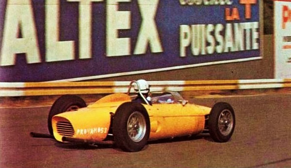
Here's a question for you...How would you make the rear deck Weber cover for Gendebien's yellow Spa car?
Patrick
|
|
Deleted
Deleted Member
Posts: 0
|
Post by Deleted on Nov 7, 2014 1:53:19 GMT -5
Wow, very cool
I met Phil Hill one time! At his house no less. He had a Packard in his garage.
|
|
Deleted
Deleted Member
Posts: 0
|
Post by Deleted on Nov 8, 2014 11:46:00 GMT -5
Here's a question for you...How would you make the rear deck Weber cover for Gendebien's yellow Spa car? Patrick Nice question, Patrick... I though about it a little... well, I'd close the two air intakes of the 120 degrees version with a styrene piece inside et a lot of two-components putty outside... then, i'd open the central big intake for the 65° version, I'd shape it with Dremel, files and sand paper, then I'd make the raised edge of the intake with a metallic wire super-glued around the opening and puttied and sanded, in order to be continued with body surface... using two-components putty like Milliput, Tamiya etc., it should be possible even to drill the holes for the rivets... finally I'd shape the metallic mesh with a properly shaped piece of wood or styrene, pushed on the mesh from beneath... I hope that my italian thinking has been understandably translated...  I'm honoured that a pro like you wants to discuss with me about a transformation, thank you! |
|
Deleted
Deleted Member
Posts: 0
|
Post by Deleted on Nov 8, 2014 11:52:42 GMT -5
Wow, very cool I met Phil Hill one time! At his house no less. He had a Packard in his garage. thank you Hubie... lucky for the meeting with Phil Hill, I greatly estimated him.... not a phenomenon like Clark or Moss, according to me not at the level of the British Hill, Graham, but fast enough and very consistent and reliable... a very fine driver and a real gentleman in his life... |
|
Deleted
Deleted Member
Posts: 0
|
Post by Deleted on Nov 8, 2014 12:46:37 GMT -5
well, today I finished the model, but here we are still in the middle of the WIP... and I don't want to reveal anything... After the last works on the body, it was finally painting time; before, big masking task:  Then, primer coats...  ...and finally the Rosso...  After removing the masking tape, I corrected with the brush the little painting damages on the suspensions and I mounted the wheels... the ones supplied with the kit are really ugly (old white metal spoke wheels), so I've chosen the ones by Fermando Pinto: they are all-resin wheels (rims, tires, hubs) with hand-laced metal wire spokes... they are quite expensive and turned aluminium rims wheels are surely better for a similar price (I payed them around 42 $), but 1) the hand-laced spokes are very nice and more realistic if compared to photoetched spokes, 2) these wheels correctly reproduce the difference between the front and rear spokes' pattern; 3) the resin hubs can easily fit any kind of pivot with a minimum of work; 4) I love resin tires, as they don't go bad with years...  So, I mounted them on the suspensions, after having added the exhaust pipes...   Ok, enough for today... last night I worked hard (two urgent coronary angioplasties for myocardial infarctions) and now I go to rest... |
|
|
|
Post by Patrick on Nov 8, 2014 14:38:52 GMT -5
Bevita, You are similar to me in that I would build models to get my mind off of being a teacher and take a brain break! However, I see now where your patience lies! Excellent work and those Pinto wheel'tire combo cannot be beat! I have a set for a M-B W159 project...lovely. As to the V6-60* engine cover...the part I'm at a quandary over is Olivier's car had a drilled holes cover (like Hill's Monoaco car) and not a mesh cover. That's what stopped me dead in my tracks! I may just give up on his car and do Ricardo's '62 car which had a clear plastic cover (but alas not the wonderful yellow body!!). I have that part ready to mount... 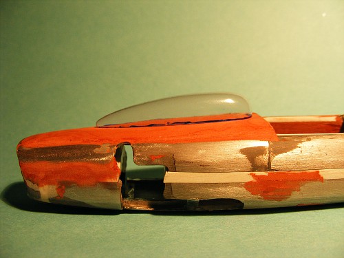 well, that rests as one of my unfinished projects! 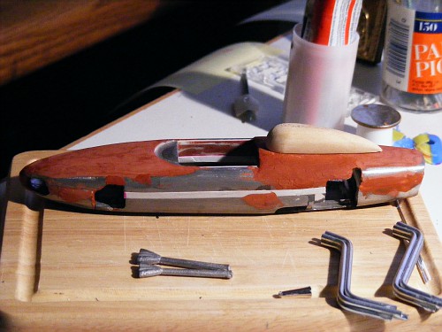 The Finecast kit isn't as good as the Pinto one, but I was able to get a damaged one for cheap! I used the suspension on the Trips '60 Monza F1 prototype model I made. Patrick |
|
Deleted
Deleted Member
Posts: 0
|
Post by Deleted on Nov 8, 2014 16:45:00 GMT -5
Ok, Patrick, I finally got what is your real problem... I wonder if it's really sure that the Gendebien's car cover was drilled holes... are there some clear images of that era? I know the car was recently replicated in USA, but that is in any case a replica, albeit excellent and with many original parts.... However, reproducing the Rodriguez car seems to me an excellent solution, it isn't yellow but the transparent cover is very charming....  |
|
|
|
Post by beardogracing on Nov 8, 2014 19:10:33 GMT -5
|
|
Deleted
Deleted Member
Posts: 0
|
Post by Deleted on Nov 9, 2014 2:41:51 GMT -5
Thank you Beardog, but these images don't help enough... is that mesh or drilled aluminium?
|
|
Deleted
Deleted Member
Posts: 0
|
Post by Deleted on Nov 9, 2014 17:56:17 GMT -5
|
|
|
|
Post by Patrick on Nov 9, 2014 19:12:30 GMT -5
Looks very nice. I'm having some help in finding a better photo of Olivier's carb cover...more to come.
Patrick
|
|
Deleted
Deleted Member
Posts: 0
|
Post by Deleted on Nov 10, 2014 2:34:34 GMT -5
Good luck!
|
|
Deleted
Deleted Member
Posts: 0
|
Post by Deleted on Nov 10, 2014 13:00:39 GMT -5
Mike Lang's "Grand Prix Racing" has a picture of it but it is black and white
|
|
|
|
Post by Patrick on Nov 10, 2014 17:34:53 GMT -5
Here's one source for a good photo of the "drilled screen"... 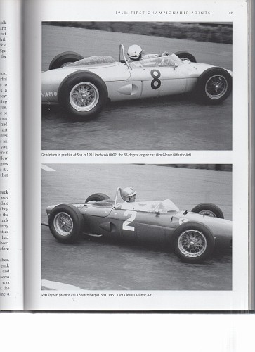 and enlarged view only brought out the images patterning... 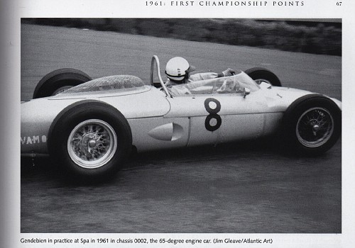 I think I have this image (cleared of the patterning) stored somewhere...that's somewhere! Patrick |
|
Deleted
Deleted Member
Posts: 0
|
Post by Deleted on Nov 11, 2014 0:31:41 GMT -5
According to me, it's too transparent to be drilled aluminium...
|
|