Deleted
Deleted Member
Posts: 0
|
Post by Deleted on Jan 31, 2016 5:54:08 GMT -5
Some good progress this week. The holes in the engine for the exhaust headers are much too big. Styrene plugs were inserted and then the holes redrilled to make a nice snug fit.  There is a part that attaches to the left side of the transaxle (starter motor?). I machined a replacement from styrene. 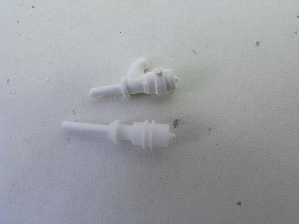 The kit parts for the injectors are upside freakin' down! Here's what I did to remedy: - drilled holes in the bottom of the injectors to accept a styrene pin - drilled holes in the bottom of the plenum - glued the injectors to the plenum and let dry overnight - carefully cut the injectors apart to 1) make painting easier as there are multiple colours and 2) allow a piece of red shrinkwrap tubing to simulate the hose on the real car    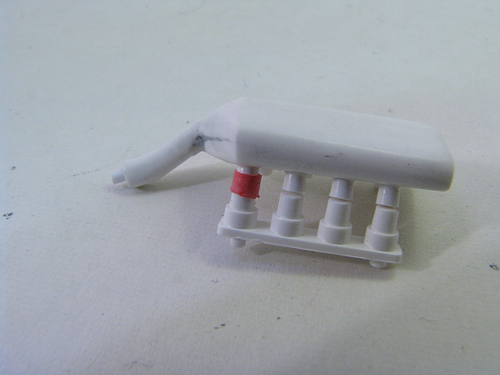 The rear wing mounting plates were also cleaned up and thinned down.  The distributor/fuel pump unit is also mounted facing the wrong way on the kit. I've drilled out the holes and have used some nice Scale Dreams orange wire for the spark plug wires and coil box.  Later |
|
|
|
Post by indy on Feb 1, 2016 10:14:29 GMT -5
Love the progress. FYI, pretty sure that piece is not a starter, just watched the intro to the 1979 500 and they all used external starters. Still a nice job on machining a replacement for it though.
Jordan
|
|
Deleted
Deleted Member
Posts: 0
|
Post by Deleted on Feb 1, 2016 17:54:14 GMT -5
It's a wastegate isn't it?
|
|
|
|
Post by 2lapsdown on Feb 1, 2016 18:44:19 GMT -5
I think it's a wastegate too. Doesn't the remote starter plug into a shaft on the gearbox?
John
|
|
|
|
Post by Calvin on Feb 2, 2016 1:51:55 GMT -5
Its the wastegate....no on-board starters on Indianapolis cars.
|
|
Deleted
Deleted Member
Posts: 0
|
Post by Deleted on Feb 7, 2016 9:47:36 GMT -5
Thanks everyone for the help on the 'thingy' attached to the transaxle - "I think I've got it, by jove". It is a wastegate and I examined the photos from Harveythedog2 more closely and figured out that there is a pipe that runs from the input of the exhaust side of the turbo, to the wastegate. It now makes sense that the pipe hanging off the side is actually where the exhaust gases would exit when the wastegate kicks in. I used some 1.5 mm diameter solder and after about half an hour, got it bent just about right. Here's how it was set up originally. 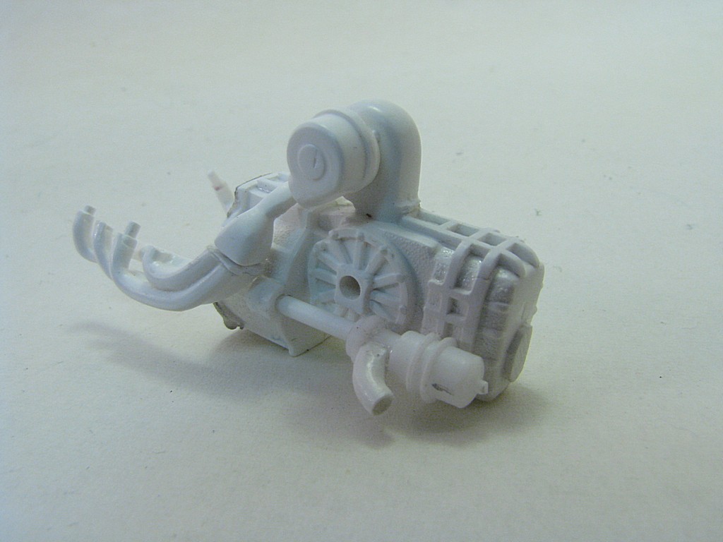  And after ![]()  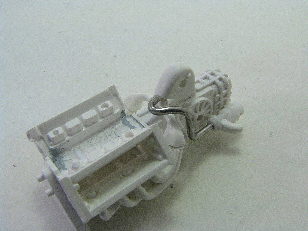 The engine should be pretty well mocked up this weekend. |
|
|
|
Post by Gary Davis on Feb 8, 2016 15:17:45 GMT -5
Man...this is a very good WIP. Excellent craftsmanship. Waiting for the next up date!!
|
|
|
|
Post by indy on Feb 8, 2016 16:12:08 GMT -5
Great to see this work going into this kit. I am really enjoying the updates - thank you!
Jordan
|
|
Deleted
Deleted Member
Posts: 0
|
Post by Deleted on Feb 15, 2016 20:14:54 GMT -5
For a bit of a change of pace, I decided to tackle the front suspension. I always like to add poseable steering to my models, and most domestic manufacturers don't design this into their kits. First step will be to add an attachment point for the tie rod using a small piece of sheet styrene. The kit hub/brake piece is on the right, the modified piece on the left.  The sequence was the following: - fill in the hole in the lower 'A' arm with a styrene rod - cut off the little nub at the bottom of the upright - drill holes to accept some 0.80 mm (0.32") diameter aluminum wire in the lower arm and 'upright' - shape the lower 'A' arm so it isn't so bulky - carefully separate the 'upright' from the upper arm with a photoetch saw - drill more holes for wire in the upper arm - attach the 'upright' to the front hub/brake unit - repeat for the other side Completed parts on the right, original parts on the left.  |
|
|
|
Post by indy on Feb 16, 2016 10:11:44 GMT -5
Somehow I missed your rear suspension update. I am impressed by your work on both the front and the rear suspension, really nice job on improving this kit.
Jordan
|
|
Deleted
Deleted Member
Posts: 0
|
Post by Deleted on Feb 21, 2016 16:08:15 GMT -5
I did some work on the front roll bar. I first cut down the very large round piece that is supposed to hold the steering wheel shaft. There are no locating pins for the roll bar and in order to make sure that the everything stayed in place, I made some pins out of 0.5 mm diameter craft wire. I then drilled two holes in the tub to accept some 1.2 mm diameter support rods. These were carefully glued and let set overnight. The following day I dabbed some thick CA glue on the joint to strengthen it and to add some simulated welds. I will add some styrene gussets later.   You can see the pins I added for the roll bar. You can also see that I used a similar technique with the front suspension upper arm, using some thicker wire. 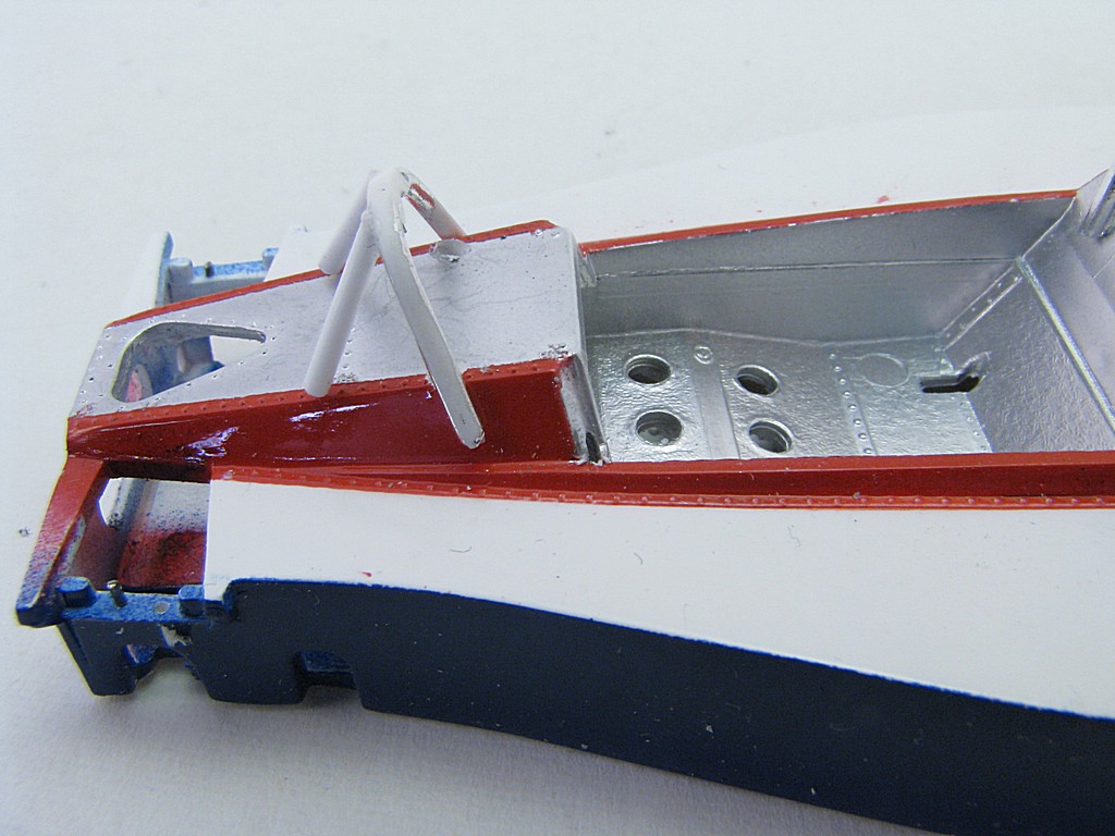 I've been debating whether I should leave the upper fuel filler alone or make a suitable filler tube. I eventually bit the bullet and from the backside, carefully sliced and sanded where the fuel filler is molded into the cowl. I machined a new filler cap out of aluminum and added a bent piece of 3 mm diameter solder for the tube. Again, the tube will need some gussets later.  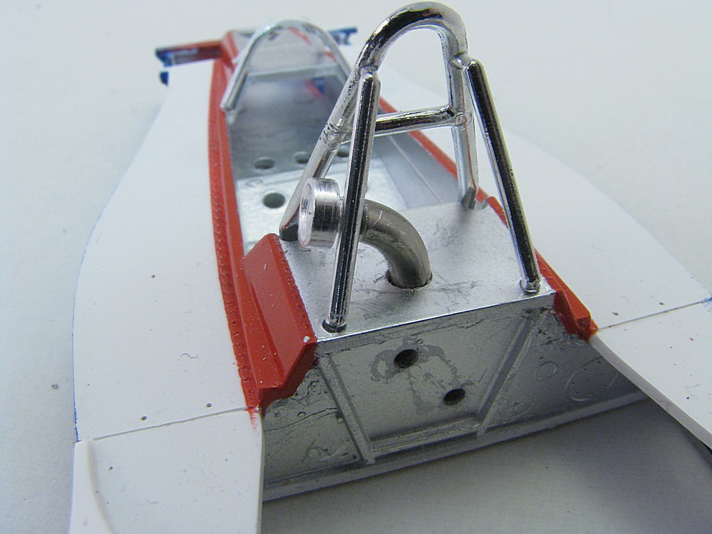 As you can see, I've scratched up some of the Alclad aluminum and have resigned myself to the fact that I will be repainting all, or some of the tub: - I want to add the lower fuel filler to the left side - there are a couple of scratches in the white paint that need to fixed. - there are a couple of places where I didn't clean up some red paint flakes before I clearcoated - the red was painted over Alclad polished alumnim and there is a noticeable difference between the cowl red and the tub red - there are a few areas that weren't masked off completely (e.g. the red overspray at the end of the tub and some blue overspray in the area of the front suspension.) I will probably strip the tub this week and hopefully get to repainting next weekend. |
|
|
|
Post by indy on Feb 22, 2016 11:13:36 GMT -5
Nice scratchbuilding and machining - really enjoying all of these updates. Best of luck with the paint.
Jordan
|
|
Deleted
Deleted Member
Posts: 0
|
Post by Deleted on Feb 28, 2016 13:15:39 GMT -5
This week's update. Before I get started, here is a photo of the front roll bar before it got modified.  After spending 5 days on and off in Castrol Super Clean and a few hours of clean up, almost all the paint came off. I added some gussets to the front roll bar connection points and the fuel filler joint. These are pieces of 0.25 mm (0.010") sheet styrene, which is maybe a bit too thick.  I also drilled a hole for the lower fuel filler (that's what it looks like to me). A filler was machined from plastic rod so that it just fits in the hole - plastic because it will be painted semi-gloss black. The bodywork plastic is pretty thick here and the hole has a bit of a taper on it so that the cap fits just flush with the bodywork.   The suspension bars have been replaced with 1.3 mm (0.50") diameter styrene rod and fit into holes drilled in the firewall. I did a dry fit of the major components just to make sure there are no interference issues and everything looks good.   Hopefully I will get some painting started this week on the various parts. |
|
|
|
Post by indy on Feb 28, 2016 23:21:08 GMT -5
Wow, redoing the rear suspension - this just keeps getting better and better.
Jordan
|
|
|
|
Post by indycals on Feb 29, 2016 1:21:41 GMT -5
Really looking forward to seeing how this plays out.
Are you planning on adding the side skirts to the bottom of the tub?
|
|
Deleted
Deleted Member
Posts: 0
|
Post by Deleted on Mar 2, 2016 6:23:35 GMT -5
Yes, I am going to add side skirts, that will be in my next update.
Evan
|
|
|
|
Post by SWT500 on Mar 2, 2016 8:14:39 GMT -5
What you are calling a "fuel filler" is actually an access panel to the fuel cell. Once drained or almost empty, a mechanic could remove this and make adjustments to the fuel pick ups and fuel system. I never worked on one of these but on many cars, there is one on each side.
|
|
Deleted
Deleted Member
Posts: 0
|
Post by Deleted on Mar 5, 2016 11:38:31 GMT -5
Thanks for clarifying what the lower fuel filler is actually for. It never really made sense to me as a fuel filler anyway - located halfway up the side of the body, when a lot of the fuel is carried higher up between the driver and engine. I wanted to describe my ideas for the side skirts. On the real car they look to be made out of strips of rubber, which makes sense as you don't want them to catch on any bumps. My first idea was to flatten some 1 mm diameter lead wire that the armour modellers use. I used a flat nosed pair of pliers and then hammered on a piece of steel plate.  I couldn't get it thin enough, or straight enough. So I decided to try some 1.5 mm solder wire.  Results are not much better. I would still have the problem of bending down the center and attached to the underside of the body. I was then looking around my model table looking for inspiration when I noticed some aluminum duct tape. After some experimenting, this looks like it will work. I made a pattern out of 0.8 mm (0.030") sheet styrene to help cut out the duct tape and attach it. Essentially, the steps will be: - cut out a piece of duct tape with help from the pattern.  - peel off the backing and then attach to the bottom of the body. - hold the pattern onto the bottom of the body and use as a guide to bend the duct tape 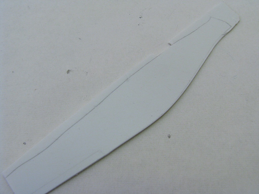 - brush paint the duct tape flat or Nato black. Here is a sample piece that I did.  I'm not sure how wide to cut the duct tape until I get the car almost completely assembled and see what the ground clearance is. I'll take the sequence pictures when I do this. |
|
Deleted
Deleted Member
Posts: 0
|
Post by Deleted on Mar 5, 2016 12:00:02 GMT -5
I repainted most of the body this week and took quite a few photos along the way. Here was the sequence: 1) prime with Gunze 1000 white primer, straight from the can 2) mask off the cockpit areas that will be Alclad polished aluminum as the final painting step. 3) mask off the white and blue areas, leaving only the red areas around the cockpit. I used the new flexible 2 mm Tamiya masking tape for the lower part of the red masking and it worked great 4) airbrush the red with decanted Tamiya Bright Red (TS-49) 5) after drying for about 8 hours, cover the red areas (I used some paper as I did not want the tape directly on the red) 6) remove some of the tape and mask so only the blue areas are left 7) airbrush the blue with decanted Tamiya Blue lacquer (TS-19) 8) after drying overnight, remove all the masking tape except for the cockpit area 7) spray 3 coats of Tamiya clear, about 30 minutes apart   An hour of masking and 5 minutes of airbrushing.   About 45 minutes of masking and 5 minutes of airbrushing.  Ready for clear coating At the end you have a big pile of masking tape pieces, with more to come. Four colour paint schemes are always interesting.  After letting the clear coat dry, I will remove the tape in the cockpit area, mask so the aluminum areas are exposed and airbrush. Probably not this weekend. I will be away for the next two weeks and won't have any updates until probably late March I will actually be at the West NNL on March 12 if any of you are in that area. I'll have the following models: - 1:20 Honda RA272 www.eajonesgue.com/scalemodels/HondaRA272.html- 1:12 Honda RS1000 race bike in gulf colours www.eajonesgue.com/scalemodels/HondaRS1000Gulf.html- 1:12 Suzuki Katana drag bike www.eajonesgue.com/scalemodels/SuzukiKatanaDragBike.htmlLinks should take you to a page I put together for each model |
|
|
|
Post by racerbrown on Mar 5, 2016 18:01:31 GMT -5
great problem solving sir!
thanks for sharing.
duane
|
|
Deleted
Deleted Member
Posts: 0
|
Post by Deleted on Mar 19, 2016 15:23:22 GMT -5
Just a quick update this weekend as I only was able to do some work on Saturday. The remaining masking tape was removed and the body was remasked, leaving only the cockpit and firewall exposed. Along with all four brake disks, the rear push bar, the air plenum and the oil tank, it was airbrushed with Alclad polished aluminum. I find the polished aluminum a little more forgiving than the chrome and it looks good even over bare white plastic. 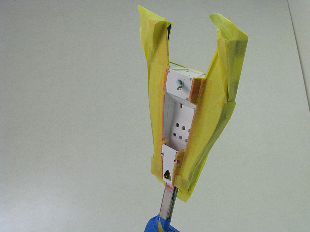  (Forgot to set the macro mode on the camera, so the picture above is blurry) 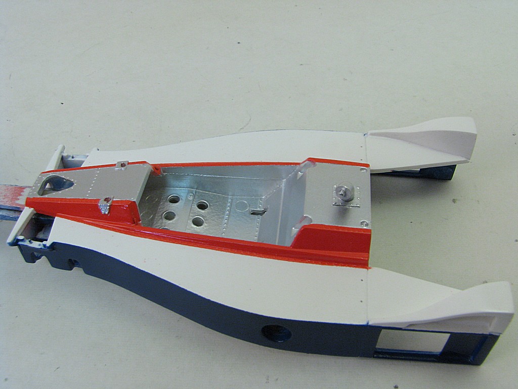 Around the front roll bar brackets and the fuel filler, I added some rivets. This was done by dipping a toothpick into white glue and dabbing onto the model. A little bit misshappen, but a quick way to add rivets. Thanks to Randy Derr for this tip.  With the long weekend coming up, I hope to get the rest of the parts painted and maybe start on some final assembly. |
|
Deleted
Deleted Member
Posts: 0
|
Post by Deleted on Mar 21, 2016 16:22:52 GMT -5
Super nice build of a difficult kit.
I'm impressed, super clean. Nice attention to detail. I built one years ago and gave it away. I built a second one for my collection
I will give it away now and use this as a guide! (possable wheel option not important to me, but cool just the same)
BRAVO!
|
|
|
|
Post by indy on Mar 21, 2016 21:03:04 GMT -5
Another great update, thanks for letting us keep tabs on this one. I love to see what is being done on this build.
Jordan
|
|
Deleted
Deleted Member
Posts: 0
|
Post by Deleted on Mar 27, 2016 15:32:40 GMT -5
I managed to get some work done on brush painting the remaining small parts and assembling the engine this weekend. Here are the engine parts laid out.  I decided to put a 3 mm diameter piece of brass screen at the bottom of the turbo air inlet.   I spent about 45 minutes routing the fuel lines. These turbocharged. Cosworth engines don't seem to have the same fuel line configuration as the naturally aspirated engines. The fuel lines were made of 0.3 mm clear fishing line, marked with a red Sharpie pen. I'm showing the photo now because when the air plenum is installed (you guessed it), the lines are almost impossible to see.    The exhaust hasn't been glued in just yet, still needs a bit of tweaking. Bare Metal Foil on the upper engine mount brackets. |
|
|
|
Post by indycals on Mar 27, 2016 16:21:17 GMT -5
This is spectacular!
|
|
|
|
Post by clm1545 on Mar 27, 2016 22:00:55 GMT -5
Really nice work. It's looking just super!
|
|
|
|
Post by Calvin on Mar 28, 2016 0:57:25 GMT -5
Always impressive!
|
|
Deleted
Deleted Member
Posts: 0
|
Post by Deleted on Apr 11, 2016 20:46:54 GMT -5
I haven't finished a whole lot over the last two weeks. The seat belts are in (Hobby Design photetch and Tuner Model Manufactory seat belt material). The material has an adhesive on the back, but's it's not sticky enough. It's anchored with some resin hex head bolts from MasterClub (0.8 mm, I think). I would pay a lot extra for pre-assembled seat belts, they are very finicky to put together.  The instrument panel and gauges are in, with some wiring and a Top Studio toggle switch. Since I don't have any cockpit photos, there's a lot of artistic license used here. I'll have to scratchbuild a gear shifter as the kit does not have one.  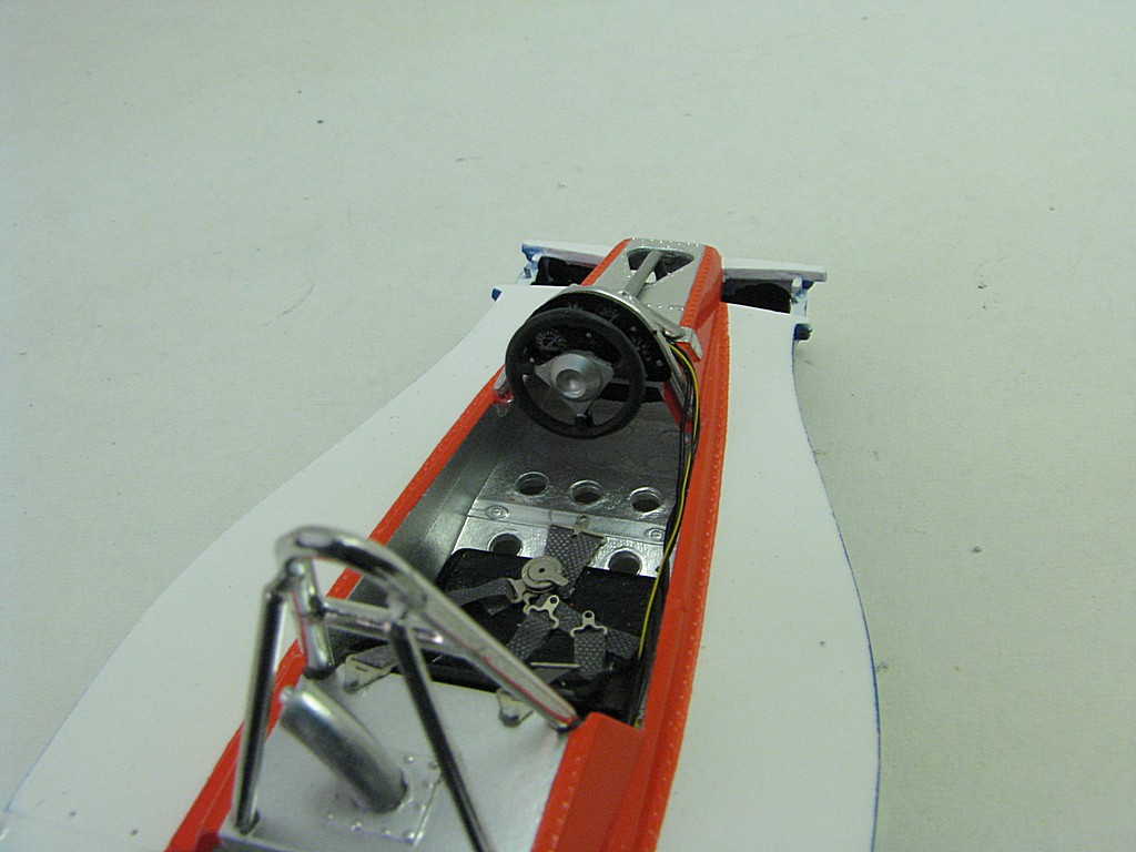 The goal is to have the model finished for the Kingston (Ontario) Modelrama show on April 24. |
|
|
|
Post by Calvin on Apr 11, 2016 23:33:33 GMT -5
This is really taking shape! You really got that realistic look going on!
|
|
|
|
Post by macsparty on Apr 12, 2016 12:44:56 GMT -5
It is so great to see this venerable old kit getting such love. This was the first Indy car kit I ever did when I was a kid. Let's just say it didn't turn out this well.  |
|