Deleted
Deleted Member
Posts: 0
|
Post by Deleted on Nov 10, 2014 10:55:08 GMT -5
I've been looking all over the net for some information on the brake cable routing for the 91 RD. In my never ending quest to cram way too much detail in a given square inch, I'm trying to add brake rigging to my Etzel car. All I can tell for sure is that they are definitely not the same as the FD cars. HELP!
|
|
|
|
Post by johnwebster on Nov 13, 2014 0:48:00 GMT -5
|
|
Deleted
Deleted Member
Posts: 0
|
Post by Deleted on Nov 13, 2014 11:42:16 GMT -5
Been there. Thank you for the reference. It seems nobody has made photos of this area of the car. Just try to find a good shot of the tie rod/ends. I'm afraid most of the pictures you'll find are 'glamour' shots, and brake cables and links ain't so glamorous. I think I can infer most of all this through photographic 'circumstantial evidence'. Back to the bench!
Bill
|
|
|
|
Post by racerbrown on Nov 13, 2014 20:45:43 GMT -5
hey bill, i've got some cd's from the millers at milwaukee. i'll see if i can find something. duane 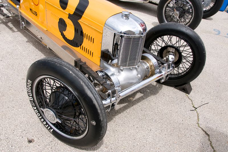 |
|
|
|
Post by johnwebster on Nov 14, 2014 21:41:28 GMT -5
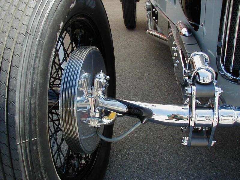 This is the V-16 but some pics of other rear drives show the armored cable coming out of the open end of the straight section of the axle tube and entering the backing plate directly below the kingpin. |
|
|
|
Post by racerbrown on Nov 15, 2014 0:02:50 GMT -5
no brake lines but still a cool shot. duane 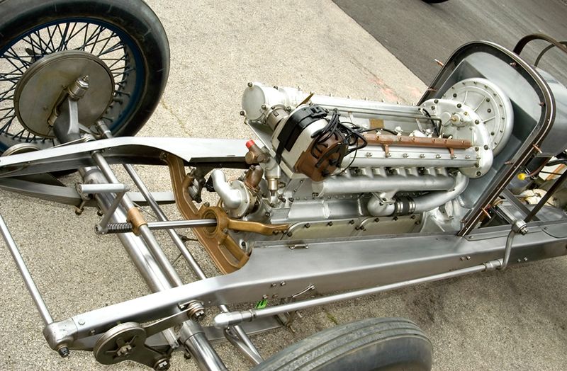 |
|
|
|
Post by johnwebster on Nov 16, 2014 2:57:39 GMT -5
We're missing an obvious clue: look just ahead of the bottom of the bronze front engine mount. There is the front brake wire. On the completed car it is inside the belly pan. Hidden under the tie rod is a plate with the right and left brake wires connected to its ends. They run forward to the front axle tube. I would bet that there is a slot in the rear of the axle tube where the wire enters, probably with a pulley or rubbing block to keep the wire from fraying.
Curiously enough, the starter crank is engaged in this picture. If it was disengaged there would be space between the coils of the spring between the handle and the bronze bracket.
|
|
|
|
Post by racerbrown on Nov 16, 2014 8:31:56 GMT -5
sharp eyes there john!
duane
|
|
Deleted
Deleted Member
Posts: 0
|
Post by Deleted on Nov 19, 2014 13:06:02 GMT -5
The best picture of the cable routing that I have found so far is in a shot taken down low and in front in very dim light. If you blow this shot up to fill your screen, you be able to see where the armoured cable enters the axle outer tube. You will also be able to see about where it exits. It exits where the outer 'shrunk on' tube ends inboard. From there the two cables lose their outer jacket about 9-10 inches from the tube. There is functionally only one cable, which runs between the brake drums. Between the tubes where the cable(s) exit near the center, a bunch of slack allows the cable to run through a pulley which is located behind and below the axle. This pulley locates in a bracket with a lever of some sort. The pulley is, by the way, the equalizer for the front brakes. I'm sure there is one (out of sight) at the rear as well. That is how cable brakes work without jerking the car to the side when activated. (I don't know if I'm happy I remember this!) It never worked all that well. The part I can't make out is the actuating lever somewhere between the engine and that pulley. I can see it all, just can't quite make out what's what. I do know this: There is a lug cast onto the sump at the right front lower corner with a hole drilled through, front to back. The cable terminates at that point and a rod takes over from there. If you look carefully at some of the right side views of the car, you can make out this rod running parallel to the various ribs and features that go from front to rear on the pan. That rod is the part that disappears in to the belly pan. It's what's between those two points (pulley and oil sump) that I'm trying to figure out. What's intriguing is that the pulley/cables seem to be centered, yet the rod runs alongside the engine. I've got some ideas, but I really like being accurate, just like the rest of you, and I don't like just faking it, though in a relatively restricted view site, I have persuaded myself to 'imagineer' a component in a way that makes sense. Shame on me.
By the way, you can see this on the restored Perfect Circle #2. Google up 'Miller 91 Rear Drive' and go to images. Look for the picture taken in rather dim light from the left front down low. Turn up your brightness and enjoy the wealth of detail visible from this unusual angle.
What's weird is that I have seen and touched this very car. It lives about a half a mile from me, though worlds away from a financial standpoint! The owner has allowed me to photograph it from any angle (It's amazing how many you forget to take), climb all over it, sit in it, (WOW!), and measure whatever I like. I have been to this guy's garage a couple of times. You should see the collection of Miller parts he has. I have held engine and running gear parts that Harry Miller himself handled. It is an honor. Problem is, he's out of the state for a while and this is the part of the model on which I am concentrating now, and I'm an impatient sort. I may have to wait, dammit! Does anyone have a particular part of this machine they'd like detailed pictorially? If and when I gain access again, I will be taking a LOT more pictures.
|
|
Deleted
Deleted Member
Posts: 0
|
Post by Deleted on Nov 19, 2014 13:25:58 GMT -5
Hey racerbrown, I just noticed something on the frame picture you posted; and thanks a bunch for doing so. I have been researching this car for so long I think I ought to own it. Anyhow, if the car depicted is indeed a 91 RD, it has the wrong front axle. The enlarged section where the spring perches mount should continue all the way to the outboard ends and form the kingpin 'webs'. This axle is likely from a 122, which used this scheme. I fear I'll wear out my copy of "Miller Dynasty" looking back and forth through it and studying the technical drawings through an Optivisor. I bet that is the view of the world plenty of us have for large periods of time...
|
|
|
|
Post by tomfaletti on Nov 20, 2014 9:31:38 GMT -5
I'm pretty sure the picture of the Miller with the body removed, that Duane posted, is a replica of the Cliff Durant owned JR8 Special 122 driven by Earl Cooper in 1925. He qualified 4th and finished 17th after wrecking in turn one on lap 127. Great shot Duane.
|
|
Deleted
Deleted Member
Posts: 0
|
Post by Deleted on Nov 20, 2014 15:32:59 GMT -5
Duane, I didn't mean to give you short shrift on that picture. It is helpful in so many ways. The Jr 8s shared so much in common with the 91 RDs that this is useful in either case. The detail is terrific and will indeed help me in my quest. I've seen this same chassis online, but it was from head on. This one is much more helpful.
Thanks again.
Bill
|
|
|
|
Post by racerbrown on Nov 20, 2014 21:05:27 GMT -5
no worries bill.  it's all good. duane |
|
Deleted
Deleted Member
Posts: 0
|
Post by Deleted on Nov 23, 2014 14:03:08 GMT -5
Well, shut my mouf! After further study (My eyes can no longer focus and my head aches) I've discovered that the brake rod previously described by me as running from the lug on the right front lower corner of the sump is indeed also armored cable. The jacketing ends just before the cable enters the belly pan. I've also noticed that no two 91s are the same in detail at all! Some whole systems were different, They used different numbers of spring leaves, the blower housings differed in material and detail, and a whole raft of other things. As Dees states in his book, and as I have discovered on some close inspection, they were customized immediately or after a few runs by their owners. He goes on to state that there is virtually no such thing as an intact restoration and that some methods/details were lost and 'dealt with' by their restorers. The cars were never intended to be collectible, and therefore suffered various fates, mostly ugly. When I looked at my neighbor's Perfect Circle #2, there were as many questions as answers. Mixing and matching through purchase and bargaining over used parts, plus whole frames and bodies being fabricated sort of thin out the gene pool. Serial numbers are practically useless in identifying a given car. Who cares? They are beautiful no matter what.
|
|
Deleted
Deleted Member
Posts: 0
|
Post by Deleted on Nov 23, 2014 14:06:51 GMT -5
By the way, the Perfect Circle has 6 spring leaves on each front, and I THINK 7 on the rears. No, I decided not to solder them up out of brass stock. This thing is kicking my butt for time as it is. Maybe when I do the Front Drive where they can be seen better...
Bill
|
|
Deleted
Deleted Member
Posts: 0
|
Post by Deleted on Dec 14, 2014 15:57:38 GMT -5
Well, I did it again. I relented and silver soldered up a set of leaf springs for the front suspension. Being obsessed with detail I also made the bottom spring fastener plates and the rear shackles; all from sheet and strip brass and stainless tubing. If anyone's interest I'll post pics of my progress to date, including the stainless front axle. Am I already nuts and can't see it? or am I just on my way...
|
|
Deleted
Deleted Member
Posts: 0
|
Post by Deleted on Dec 15, 2014 21:23:12 GMT -5
any pictures of this build? sounds fantastic.
|
|
|
|
Post by racerbrown on Dec 16, 2014 19:59:36 GMT -5
hey bill,
we'd love to see pictures of your progress.
duane
|
|
Deleted
Deleted Member
Posts: 0
|
Post by Deleted on Dec 29, 2014 17:01:30 GMT -5
I will post pics of all this insanity as soon as I get set up (read: Figure out) to do so. I think I'm almost there. I finally woke up and found it in the intro section.
|
|
Deleted
Deleted Member
Posts: 0
|
Post by Deleted on Jan 12, 2015 15:25:40 GMT -5
Well, I THINK I've about figured this photo posting stuff out, though I'm not sure just how I got to this point, so here goes. After its 'wreck' , the beautiful Etzel 91 RD lost most of its front suspension and running gear. I plucked the engine and grill to give more room to work on the axle. The relative failure is obvious in this first photo. I used 1/16th wire as a core and added aluminum tubing, finally epoxying it all together. The displayed result was expected.
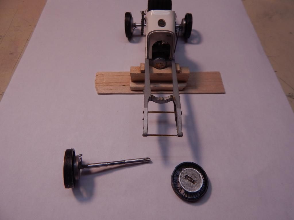
I decided in the end that a new axle, fabricated from stainless tubing, was going to be the only viable solution. Below is one side at the beginning, with three sheets of stainless sheet stack soldered and roughly shaped inserted into the slot dremeled and filed out. The next step was a very generous helping of silver solder for shaping the 'casting' effect of the hub carriers. 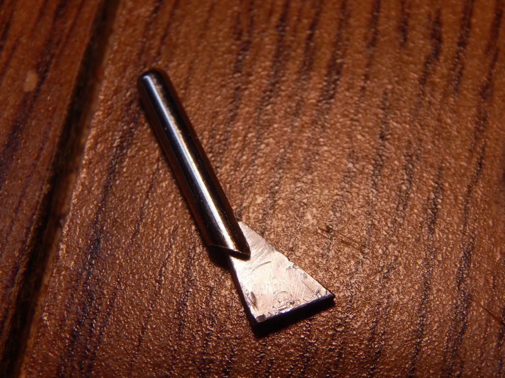
Here I have shaped the left front axle section and fabricated a steering arm. The arm is made from brass with a coating of 'poor man's chrome' (silver solder sanded and polished) The finished thing will not steer. Next time maybe. It would be great on the front drive when the budget allows. 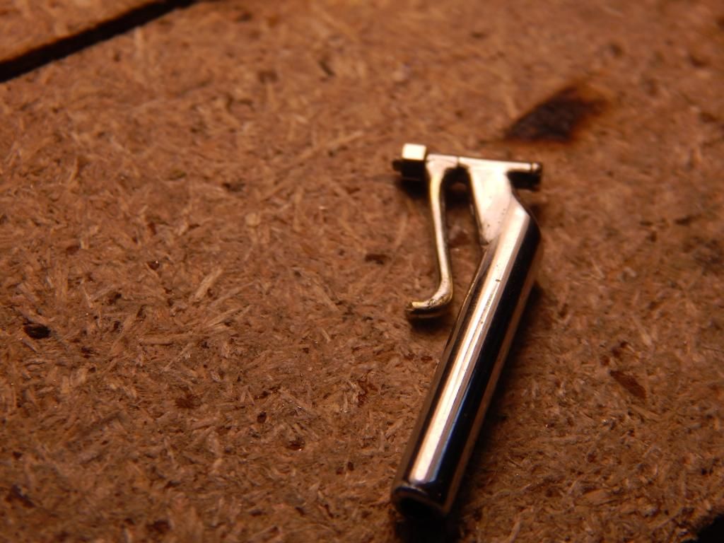
Here is the finished front axle. All told, there are 14 pieces involved, beginning at the center with a piece of 1/16th carbon fiber rod. The mount pedestals have been soldered on and blended as on the prototype. 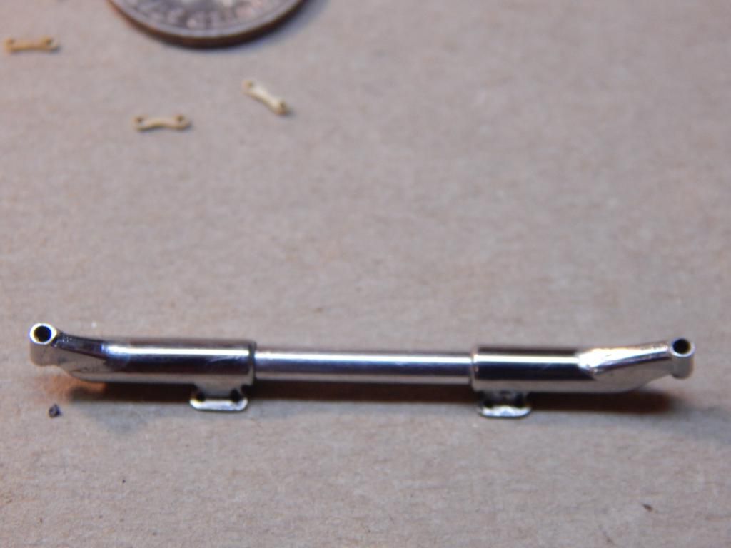
Here are shown the leaf springs I swore to myself I wouldn't do. I guess I'm not a very good persuader of myself. The mount plates still need some filing and the stainless end eyes (medical tubing) need to be trimmed down, as well as a thorough clean-up around the rough edges before paint prep. 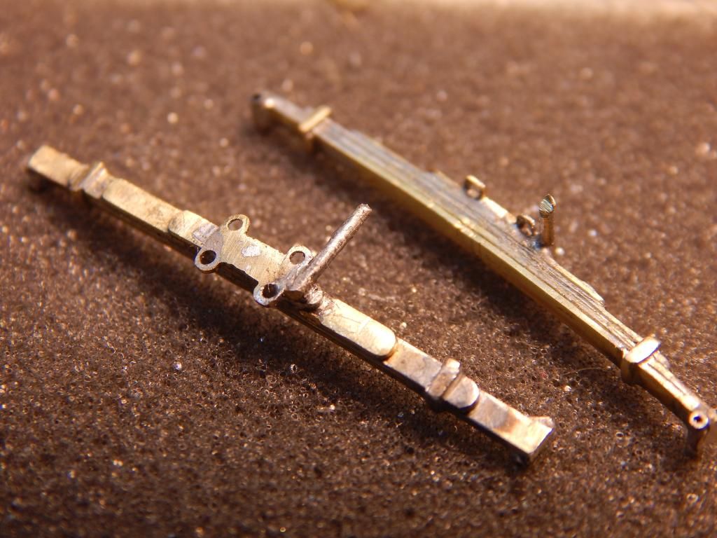
Above the dime at 12 o clock are the ends for the steering drag link. To the right are the tie rod ends. To the left; the trailing arm rod ends which mount at the frame roughly below the cockpit. Below the coin are the rear hangers for the front springs. 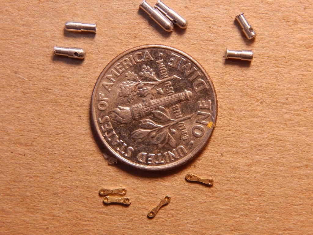
The front brake drums/back plates were turned from aluminum with the one nearly useless fin in the middle. The plates (there is one spare) will be mounted to the axle and to the spring bottoms. I'm not sure yet what to use for the connecting bolts. Any ideas? The brass tubes are for working the part. They will either be trimmed down for front spindles or removed and replaced with whatever. 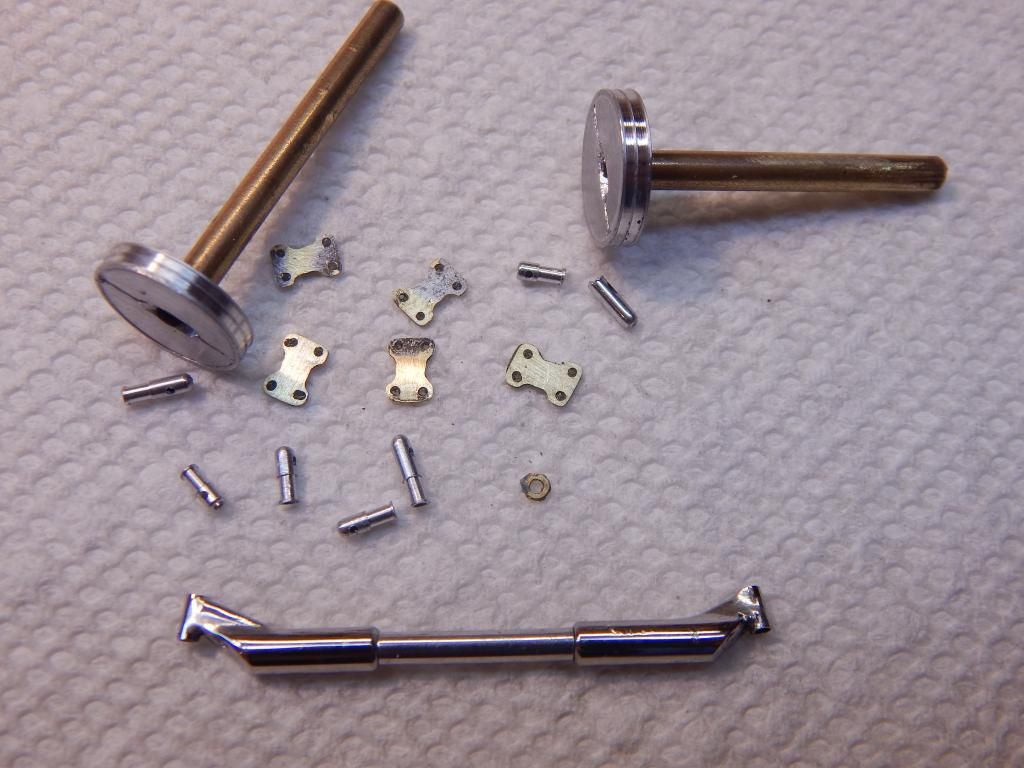
I studied each photo I could find of the front end, and observed that while some cars had a crossmember installed such that it would serve as the front spring eye mount, others had the front springs mounted in the frame and these extension brackets carried that tube. The car I'm depicting is Meyer's AAA championship #1, and it remained this way throughout that time. Look at the picture in your copy of 'Dynasty' and you'll see this. If you use your search engine to bring up images of 91s, go to the restored Perfect Circle #2 and it can be easily seen. Anyway, slots were sawn into the frame and sheet styrene was glued and subsequently shaped as well as I could. 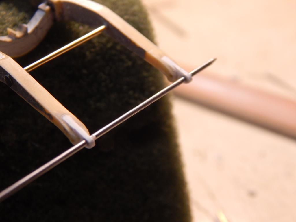
Since these photos were made I have separated the body from the frame, which I have stripped for a respray. I never was happy with the original anyway. I've also made rear drums and am replacing the straight pin brake handle with a proper tapered flat one (more phony chrome). I've also made a correct strap type exhaust clamp to replace that pin too. Next I need to find something suitable for a correct gearshift lever. I have mounted the tires on a mandrel and rounded them off on the lathe. They look MUCH better. I can't wait to get to the lettering. I have one problem. When I originally built this beauty, I used the wrong hood side panel (non-exhaust side). I used the one with the scoops instead of the louvered one. I have the panel, but I'll need the lower half of a #1. Help! Am I going too far with all this? That's the motorbill way; unfortunately for father time and me.
Motorbill |
|
|
|
Post by Patrick on Jan 12, 2015 19:40:48 GMT -5
You guys that work with metals are an amazing lot!! Thanks for sharing your skills!
Patrick
|
|
|
|
Post by mjjracer on Jan 12, 2015 21:08:20 GMT -5
The workmanship on this model matches that of the real thing! Brilliant work.
I'm not a big fan of pre-war cars, but a Miller, like a Bugatti, is a work of art.
MJ
|
|
|
|
Post by racerbrown on Jan 12, 2015 23:30:12 GMT -5
so glad you're sharing this amazing build with us.
duane
|
|
|
|
Post by indy on Jan 13, 2015 9:40:39 GMT -5
Fascinating work! Thank you for sharing, it is great to watch the pieces crafted and coming together.
Jordan
|
|
Deleted
Deleted Member
Posts: 0
|
Post by Deleted on Jan 13, 2015 12:27:39 GMT -5
Thank you guys for all the positive comments. They encourage me to continue. I hope to have this thing done someday soon. I love this site! I have about a hundred in process photos of these pieces if anyone is interested in the operations involved, though I would be selective and never try to post that many. The secret to working with metal (especially brass and stainless) is prep, just like with plastic or resin. I have a number of jigs and false starts along with 'proof of concept' parts to show for my efforts. (lots of failed brake drums) Sometimes it would take six hours to jig something for a five second solder flow. Both stainless and brass are a pleasure to use because they both solder so easily and polish to a high sheen. Not only that, but it's nearly impossible to screw something up so badly that you can't save it and the parts don't suddenly crack or 'discorporate'. Boy!, does the photo-of-everything-you-do bit slow you down. But I like to have a record of what was done so I can see it later when I become incapable of doing model work; I hope some ways off. Did I mention how I love this site? If you like, I can try to create a RIP. (That's A Rebuild In Process, and far from my first) Sorry to go on so long, but I don't see many other modelers out here in Northern Colorado except for my brother, and he's into aircraft. Thanks again guys.
Motorbill66 |
|
|
|
Post by indy on Jan 13, 2015 14:00:37 GMT -5
You could always upload all the photos to your Photobucket account and post a link for those wanting to look through the whole library of pictures taken.
Quite the commitment you show. "Six hours to jig something for a five second solder flow" - wow!!
Jordan
|
|
|
|
Post by johnwebster on Jan 15, 2015 1:25:40 GMT -5
|
|
Deleted
Deleted Member
Posts: 0
|
Post by Deleted on Jan 15, 2015 15:46:08 GMT -5
......have about a hundred in process photos of these pieces if anyone is interested in the operations involved,......the photo-of-everything-you-do bit slow you down. ..... I can try to create a RIP. .... I think we would really enjoy that! this is a great project. |
|
Deleted
Deleted Member
Posts: 0
|
Post by Deleted on Dec 2, 2015 14:38:40 GMT -5
Sorry to have been out of touch for so long. Something called life (won't go into details) got in the way. I just wanted all to know I'm not some 'flash in the pan' type who abandons a site right away. There's not much to report on the #1 Miller lately except that I finally repainted the frame. Silver is tough to spray well, and I now see a couple of areas that need work/sanding. Now I get to wait for the silver to dry hard so sanding doesn't just roll the paint off. I find metallics do this more. How about you? I did get to the engine and made a tube with seven openings along its flank to serve as the ignition wire tube. (The eighth wire comes out the back end of the tube on rear wheel drive 91s)I used fishing line as ignition wiring. After sanding it for coloring, I used pointed marker pens for color. I tried for that sort of amber tan with a bit of black ticking like the original wires. The toughest part was drilling the holes for the wires in the magneto cap. I'll post pics soon, when I have made enough progress along the way.
|
|
|
|
Post by indy on Dec 2, 2015 23:52:49 GMT -5
Will be nice to see this one progress. Glad you are picking it back up.
Jordan
|
|